background image

i-on30EX/EXD 

Installation 


Page 29 

button. The two digit display will show the bus 
address for a few seconds. 


OR:

 Press 

 to make the control unit update 

its internal record of devices attached to the 
bus. The display shows: 





5.  Press 

 to accept the change to the bus. 

(You can still press 

 to return to the installer 

menu if you do not want to change the 
number of devices on the bus.) 

Note:  If you attempt to leave the Installer Menu 
when a detector/device tamper is active then the 
keypad displays a fault message telling you which 

detector/device is causing the problem. Press 


to return to the Installer Menu. You must either 
close the detector/device tamper or delete it from 
the system before you can leave the Installer 
Menu. 

Important! Saving Changes 

When you make changes to the Installer Menu the 
control unit holds those changes in temporary 
memory until you leave the Installer Menu. As you 
leave the Installer Menu the control unit writes 
those changes into a permanent store. If you 
remove all power BEFORE you leave the Installer 
Menu then the control unit will lose your changes. 
Note that this does not apply if you restore 
Factory Defaults, that change takes place 
immediately. 

Alerts After Leaving Installer Mode 

Once you have left the Installer Menu you may 
see the red LEDs around the navigation key 
glowing. A common cause of this alert is that 
there is no telephone line connected to the built-in 
communicator. If you do not intend to use the 
built-in communicator then re-enter the Installer 
Menu and disable the communicator by setting 

Communications 

– ARC Reporting – Call Mode

 to 

“Disabled”. See the i-on Range Engineering Guide 
for more information. 

Re-Entering the Installer Menu 

When you enter the Installer Menu from a keypad, 
the alarm system is effectively disabled. While the 
system is in Installer Menu: 


Any other user trying to set the system from a 
keypad will see the message “Installer on 
Site”. 


All HUAs (including radio HUAs), fire alarm 
zones, 24 hour zones and tampers are 
disabled.  

If you have logged into the system from a PC then 
the alarm system is active. 

If you need to re-enter the Installer Menu: 

1.  Make sure the system is unset and showing 

the standby screen (time and date). 

2.  Key in the Installer access code. The default 

Installer access code is “7890”. 
As you start to key in the code the display 
shows: 





When you key in the last digit of the Installer 
access code the display shows:  





Notes: 
1. You will see this screen the first time you enter 
the Installer menu on a new control unit, or if you 
have restored Factory Defaults. You can disable 
this feature by using the Installer menu option 

System Options - User Access – User Code Required

2. If you set 

User Code Required

 to NO then the 

control unit no longer complies with EN50131. 
This option complies with BS8243 only if the user 
has given written consent. 
3. If you key in an access code incorrectly, the 
display shows 

four


“stars”. Key in the code again. 

If you key in a total of four incorrect codes then 
the system locks you out for 90 seconds. 

3.  Key in the default user code (

“1234”). 

The display shows: 





4.  Press 

 or 

 to display more items from the 

menu. 

Each item appears on the bottom line of the 
display in turn, for example: 





5.  Press 

 to select that item of the menu. 

The option you selected now appears on the 
top line. If there are any sub-options for that 
selection, then the first of them appears on 
the bottom line, for example: 





You can press 

 or 

 to display the other 

sub-options. 

Defaulting Access Codes 

If the User 1 and/or Installer codes are lost then 
you must restore all user information to its factory 
defaults. All prox tags, remotes and radio HUDs 
will be deleted. 

1.  If possible, enter the Installer menu. 

Note: If you cannot enter Installer Menu then the 
control unit will start a tamper alarm when you 
open the control unit lid. 

2.  Remove mains power, then open the case 

and disconnect the battery. 

Содержание i-on30EX

Страница 1: ...i on30EX i on30EXD Security System Installation Guide Issue 6...

Страница 2: ...erting you to potential problems or hazards Each of these are marked by the words Note Caution or WARNING Note Describes conditions that may affect the proper functioning of the equipment but will not...

Страница 3: ...re Closed Circuit Connections 20 Fully Supervised Loop Connections 20 Step 7 Connect Wired Outputs 22 Control Unit Wired Outputs 22 Wired External Sounders Optional 22 Wired Outputs on Expanders 22 Wi...

Страница 4: ...i on30EX EXD Page iv This page is intentionally blank...

Страница 5: ...grammable output and an external prox reader KEY EP A range of wireless peripherals is available for operation with the wireless expanders The range includes a door contact universal transmitter a pas...

Страница 6: ...cable The Installer Menu allows you to specify all the operating parameters for an individual installation If you wish you can also connect a PC or laptop to the mini USB port on the control unit PCB...

Страница 7: ...ll affect the signal from a transmitter Please read Eaton s Security Business publication Guidance Notes for Wireless Alarm System Installations obtainable from www coopersecurity co uk for more infor...

Страница 8: ...poor at transmitting radio waves Guided Tour CAUTION All printed circuit boards for the i on30EX its expanders and keypads have been tested for Electromagnetic Compatibility EMC However when handling...

Страница 9: ...t 1 Connectors for system bus 2 Zone output and Aux power connectors 3 Plug by output connectors 4 Tamper switch 5 ADSL filter pins i on30EXD only 6 On board communicator connections i on30EXD only 7...

Страница 10: ...XD Page 6 1 Built in communicator telephone line connector i on30EXD only 2 Siren and strobe 3 Loudspeaker 4 Bus cable connector 5 Output transistorised 6 Aux power 7 Wired zone connectors Figure 3 Co...

Страница 11: ...To open the keypad first gently prise off the trim on the front and remove the two screws Next carefully lever the front of the keypad containing the PCB and display away from the keypad rear housing...

Страница 12: ...to gently push the bottom edge of the caps in with the end of a small screwdriver to start them Remove the two screws hidden underneath see Figure 8 Gently swing the lower side of the front out from...

Страница 13: ...inals for zones 4 Sounder volume control 5 Connector for data bus and output terminal 6 Jumpers for addressing and LED function 6a Addressing not used in i onEX control units 6b LED functions and RS48...

Страница 14: ...aker connectors 19 Outputs Figure 14 EXP W10 Wired Expander 1 Cable entry also behind PCB 2 Central keyhole 3 PCB 4 Relay card i rc01 connector 5 Aux power 6 Link to enable disable front rear tamper s...

Страница 15: ...sable front rear tamper switch 6 Lid tamper rear tamper behind PCB 7 Bus termination jumper 8 Addressing button 9 Fixing holes 10 Engineering keypad connector 11 Bus cable connector 12 Sounder 13 Loud...

Страница 16: ...ent drawn from the Aux terminals 12V must be included in the overall calculation CAUTION Ensure that the system does not demand more than the maximum current available from the control unit during an...

Страница 17: ...a star configuration If there are only two arms on the star then this is the same as a daisy chain configuration see Daisy Chain 1 in Figure 17 If required fit the termination jumper at the devices o...

Страница 18: ...360mA 0 58V 1 15V 1 73V 2 30V 2 88V 3 46V 4 03V 4 61V 5 18V 5 76V 380mA 0 61V 1 22V 1 82V 2 43V 3 04V 3 65V 4 26V 4 86V 5 47V 6 08V 400mA 0 64V 1 28V 1 92V 2 56V 3 20V 3 84V 4 48V 5 12V 5 76V 6 40V Re...

Страница 19: ...and location for the user Out of sight of potential intruders Do NOT site the keypad s Next to electronic equipment particularly computers photocopiers or other radio equipment CAT 5 data lines or ind...

Страница 20: ...s You can set the function of the backlights in either of two ways a Use the Installer Menu Detectors Devices Wired Keypads Edit Keypad Keypad n Backlight option See the Engineering Guide for more det...

Страница 21: ...on key will glow for 20 seconds after the last press this may be useful when the keypad is placed in bedrooms that should be completely dark at night MENU STATUS OK LED 4 Leave local programming mode...

Страница 22: ...fixing plate and then slide it a short distance parallel to the body of the prox reader 3 Slide the fixing plate away from the reader body along the cable Figure 23 Opening External Prox Reader Figure...

Страница 23: ...peakers During normal operation loudspeakers on expanders repeat setting and entry tones for the partition that the expander is allocated to During an alarm the loudspeakers repeat alarm tones Each lo...

Страница 24: ...ne Wiring Two Wire Closed Circuit Connections With version 4 02 and higher software you can connect two wire CCL detectors to each pair of zone terminals To specify the zone wiring type use the Instal...

Страница 25: ...on a KEY KPZ01 Note that the resistance values shows are examples Figure 35 Wiring FSL Zones on KEY KPZ01 When programming select the FSL resistor values for the control unit in Installer Menu System...

Страница 26: ...minal on the control unit see item 10 in Figure 3 as either CC or FSL Use Installer Menu System Options Panel Tamper Rtn By default the terminal is CC If you program the TR terminal as FSL then make s...

Страница 27: ...any other FSL resistor combinations CC wiring Eaton s Security Business does NOT recommend that you use CC wiring for this application The maximum length of wire allowable is only 6m Instead Eaton s...

Страница 28: ...PABX exchanges with or without secondary proceed indication Note The built in communicator is not suitable for connection as an extension to a pay phone or to 1 1 carrier systems Approval The built i...

Страница 29: ...nal Installer after 14 days written notice to the authorised maintainer To connect the telephone line see Figure 45 i Using a two core telephone cable strip off 5mm and feed the cable through one of t...

Страница 30: ...hen the fault is absent Tell Back Input This input is designed to allow a plug by communicator to indicate to the control unit that the user can reset the system after a system tamper The communicator...

Страница 31: ...rt pause the keypad gives a confirmation tone The display briefly shows the bus address of the keypad If there are no other keypads connected to the bus it should be b1 d51 bus 1 device 51 Keypads tak...

Страница 32: ...flashes a second Each of these sequences has the following meaning No Flashes Meaning One Communication with control unit over bus is OK Two No communication over the bus in the last 10 seconds Three...

Страница 33: ...trying to set the system from a keypad will see the message Installer on Site All HUAs including radio HUAs fire alarm zones 24 hour zones and tampers are disabled If you have logged into the system...

Страница 34: ...ctory default options without defaulting the user and installer access codes then 1 From the Installer Menu select System Options Restore Defaults Factory Defaults The display shows 2 EITHER Press to...

Страница 35: ...ed description Note make sure that you allocate keypads correctly to partitions For more information see Assigning Wired Keypads to Partitions in the i on Range Engineering Guide Assemble and close th...

Страница 36: ...er Access HUA keys active Quick set Quick omit User code reqd 2 Way Replies 2 Way Set Instant Duress Enable User reset Zone alarms 6 Zone tampers System tampers Confirmation UK Confirmation Mode Basic...

Страница 37: ...is disabled 18 Appears only if Report Mode Fast Format AND Confirmation Mode Basic 19 Shows None on i on30EXD 20 Must be activated by a Eaton s Security Business External Support Manager 21 Appears o...

Страница 38: ...r you can employ the Test Locate Bus Device option in the Installer Menu Use this option to make a selected bus device give a continuous tone from its sounder Once you have found the bus device you ca...

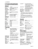
Страница 39: ...y available for at least 10 years without power Internal Clock 10 minutes over one year depending on the accuracy of the mains supply frequency User Codes 50 plus installer code Remote controls 50 one...

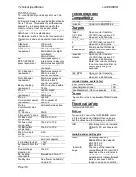
Страница 40: ...h sealed lead acid not supplied Low battery fault at 12V Aux power output fault at 9V Deep discharge protection at 10 0 5V Serviceable components Mains fuse 250mA T Standby time See Power Availability...

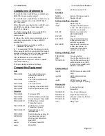
Страница 41: ...3rEUR 00 Pet tolerant PIR 714rEUR 00 PIR Transmitter Small case 720rEUR 00 Smoke Detector Transmitter 734rEUR 00 01 CC FSL Door Contact Transmitter white 734rEUR 05 06 CC FSL Door Contact Transmitter...

Страница 42: ...i on30EX EXD Page 38 NOTES...

Страница 43: ...i on30EX EXD Page 39 NOTES...

Страница 44: ...EXD Page 40 Product Support UK Tel 44 0 1594 541978 Available between 08 30 to 17 00 Monday to Friday Product Support Fax 01594 545401 email techsupport coopersecurity co uk Part Number 12435139 21 1...

Отзывы: