Handbuch/Manual
EMS-…-SWD
Elektronischer Motorstarter / Electronic Motor Starter
12/18 MN034002ZU-DE/EN
Страница 1: ...Handbuch Manual EMS SWD Elektronischer Motorstarter Electronic Motor Starter 12 18 MN034002ZU DE EN ...
Страница 2: ...der verbreitet werden Änderungen vorbehalten ___________________________________________________________________________________________________________ All proprietary names and product designations are brand names or trademarks registered to the relevant title holders Break Down Service Please call your local representative http eaton com moeller aftersales or Hotline After Sales Service 49 0 18...
Страница 3: ...baugeräte für Gehäuse oder Schränke dürfen nur im eingebauten Zustand Tischgeräte oder Portables nur bei geschlossenem Gehäuse betrieben und bedient werden Disconnect the power supply of the device Ensure that devices cannot be accidentally retriggered Verify isolation from the supply Earth and short circuit Cover or enclose neighbouring units that are live Follow the engineering instructions IL i...
Страница 4: ...mgebung A Industrie In Umgebung B Haushalt kann dieses Gerät uner wünschte Funkstörungen verursachen In diesem Fall kann der Anwender verpflichtet sein angemessene Maßnahmen durchzuführen Measures should be taken to ensure the proper restart of programs interrupted after a voltage dip or failure This should not cause dangerous operating states even for a short time If necessary emergency stop devi...
Страница 5: ... 5 3 Status LEDs 7 1 5 4 Einstellung Motorstrom 8 1 5 5 Reset 9 2 Projektierung 10 2 1 Absicherung gegenüber Kurzschluss 10 2 2 Derating Bemessungsbetriebsstrom EMS SWD 10 2 3 Auslösekennlinie 12 2 4 Stromlaufpläne 13 2 4 1 Stromlaufplan Direktstarter ohne NOT HALT 13 2 4 2 Stromlaufplan Wendestarter ohne NOT HALT 13 2 5 Sicherheitsgerichtete Abschaltung 14 2 5 1 Haupt und Steuerstrompfad NOT HALT...
Страница 6: ...5 3 Relative Stromangabe 28 3 5 4 Thermisches Motorabbild TH 28 3 5 5 Typenbezeichnung TYPE 29 3 6 Datenprofile 30 3 6 1 Besonderheiten bei Verwendung des Moduls mit dem Feldbussystem CANopen 30 3 7 Azyklische Daten 32 3 7 1 Azyklische Lesedaten 32 4 Anhang 34 4 1 Technische Daten 34 4 2 Sicherheitstechnische Funktionen 37 4 3 EU Konformitätserklärung Doc No CE1700103 38 ...
Страница 7: ...gruppe Das Handbuch richtet sich an Fachpersonal das den elektronischen Motor starter EMS DOS ROS SWD installiert in Betrieb nimmt und wartet 0 2 Änderungsprotokoll Gegenüber früheren Ausgaben hat es folgende wesentliche Änderungen gegeben 0 3 Abkürzungen und Symbole In diesem Handbuch werden Symbole eingesetzt die folgende Bedeutung haben zeigt Handlungsanweisungen an 0 3 1 Warnhinweise vor Sachs...
Страница 8: ...ersonenschäden 0 3 3 Tipps VORSICHT Warnt vor gefährlichen Situationen die möglicherweise zu leich ten Verletzungen führen WARNUNG Warnt vor gefährlichen Situationen die möglicherweise zu schweren Verletzungen oder zum Tod führen GEFAHR Warnt vor gefährlichen Situationen die zu schweren Verletzungen oder zum Tod führen Weist auf nützliche Tipps hin ...
Страница 9: ...U zur Angleichung der Rechtsvorschriften der Mitgliedsstaaten für Geräte und Schutzsysteme zur bestimmungsmäßigen Verwendung in explosionsgefährdeten Bereichen ist ab dem 30 06 2003 bindend 1 2 Geräteübersicht EMS Der elektronische Motorstarter EMS dient zur betriebsmäßigen Ansteue rung zum Schutz sowie zur sicherheitsgerichteten Abschaltung von drei phasigen Drehstrom Asynchronmotoren Hierfür ver...
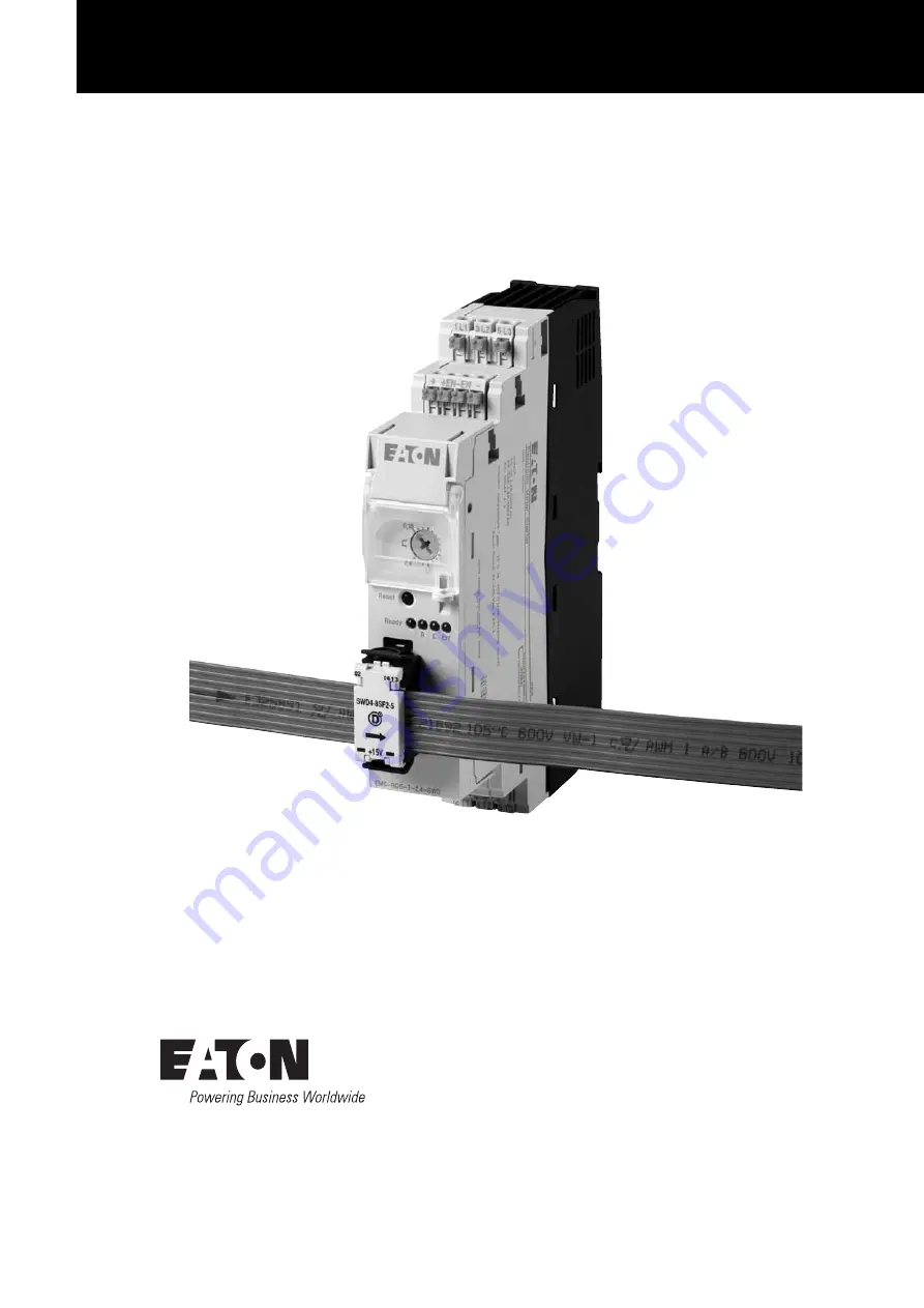
Страница 10: ...T ERR Meldung Fehler L Linkslauf R Rechtslauf ON Motor läuft EMS D d 3 Phasen Ausgangsspannung 2T1 4T2 6T3 e Anschluss SmartWire DT Gerätestecker f Reset Taster g Plombierbare Abdeckung mit Einstellrad h Anschlussklemme für sicherheitsgerichtete Abschaltung Gerätetyp Beschreibung Strombereich EMS DOS T 2 4 SWD Direktstarter mit Motorschutz und NOT HALT Schütz 0 18 2 4 A AC 51 0 18 2 4 A AC 53a EMS...
Страница 11: ...rn ist beim Anschluss an ein 3 Phasen Netz unbedingt auf die Klemmenbezeichnung des EMS DOS ROS SWD zu achten An der Klemme 8 für die 3 phasige Ausgangsspannung wird der zu steu ernde Motor angeschlossen 1 5 3 Status LEDs Der elektronische Motorstarter EMS DOS ROS SWD visualisiert mit vier LEDs seinen Betriebszustand Die LEDs haben folgende Bezeichnungen und Farben Tabelle 2 LEDs des elektronische...
Страница 12: ...w Rechtslauf des Antriebs wird durch die grünen LEDs L und R ON angezeigt Da der Direktstarter EMS D nur in einer Richtung betrieben wird ist die LED L ohne Funktion 1 5 4 Einstellung Motorstrom Über das Einstellrad Motorstrom 5 wird der Motorstrom eingestellt Diese Einstellung kann mit Hilfe der plombierbaren Abdeckung 2 gegenüber Veränderungen geschützt werden Das Einstellrad Motorstrom erlaubt ...
Страница 13: ...atenfeld ACKR Ein manueller Reset erfolgt über eine steigende Flanke Signalwechsel 0 1 des Ausgangsbits 0 3 Bezeichnung RESM Ein manueller Reset kann nach Ablauf von 2 Minuten nach Auftreten eines Fehlers erfolgen Ein automatischer Reset erfolgt über das Ausgangsbit 0 4 Bezeichnung RESA Das Ausgangsbit muss bereits vor dem Auftreten eines Fehlers gesetzt sein und für die Dauer der Abkühlzeit geset...
Страница 14: ...ich auf folgende Einbausituationen Einzelaufstellung angereiht mit 30 mm Abstand ohne Abstand Tabelle 6 Derating Bemessungsdauerstrom für Geräte EMS 2 4 SWD Schutzorgan Iq Spannung Zuordnungsart 16A gG gL 50 kA 500 V 1 30A CCMR 30 50 kA 500 V 1 FAZ B16 3 2 5 kA 400 V 1 PKM0 4 50 kA 415 V 1 PKM0 6 3 15 kA 415 V 1 Schutzorgan SCCR Spannung Zuordnungsart 20A RK5 5 kA 480 V 30A Class CC 100 kA 480 V G...
Страница 15: ...EN www eaton com 11 Tabelle 7 Derating Bemessungsdauerstrom für Geräte EMS 9 SWD Bemessungsdauerstrom Iu bei Einbausituation 40 C 104 F 45 C 113 F 50 C 122 F 55 C 131 F 60 C 140 F bei Einzelaufstellung 9 A 9 A 9 A 9 A 7 6 A angereiht mit 30 mm Abstand 9 A 9 A 7 6 A 7 6 A 5 2 A ohne Abstand 7 6 A 6 8 A 5 2 A 2 4 A 0 A ...
Страница 16: ... Auslösekennlinien ist Tabelle 8 zu entnehmen Tabelle 8 Zuordnung Auslöseklasse Bei der Verwendung der Auslösekennlinie Class 10A löst der elektronische Motorstarter innerhalb von 500 ms aus sobald der Laststrom 60 A über schreitet Abbildung 2 Auslösekennlinie Class 10 Abbildung 3 Auslösekennlinie Class 10A Gerätetyp Einstellwert Motorstrom A Auslöseklasse EMS 2 4 SWD 0 18 2 4 Class 10 EMS 9 SWD 1...
Страница 17: ... Abbildung 4 Stromlaufplan Direktstarter ohne NOT HALT 2 4 2 Stromlaufplan Wendestarter ohne NOT HALT Abbildung 5 Stromlaufplan Wendestarter ohne NOT HALT SmartWire DT 8 8 L1 L2 L3 EMS DOS SWD F1 3 L2 1 L1 5 L3 2 T1 4 T2 6 T3 M 3 EN EN W1 V1 U1 Daten für den Strombedarf finden Sie in Tabelle 3 Seite 8 SmartWire DT 8 L1 L2 L3 F1 3 L2 1 L1 5 L3 2 T1 4 T2 6 T3 M 3 EN EN W1 V1 U1 ...
Страница 18: ...erfolgen Hierbei ist zu berück sichtigen dass die Freigabeeingänge EN und EN für Helltastimpulse bis 8 ms sowie für Dunkeltastimpulse bis 3 ms geeignet sind Da die Versorgungsspannung der Leistungsendstufe nur einkanalig abge schaltet wird ist diese Art der Installation nach SIL 3 Kat 3 Kat 4 nur dann zulässig wenn ein Fehlerausschluss für Querschluss erlaubt ist Dies ist beispielsweise der Fall w...
Страница 19: ...g S2 NOT HALT S3 Reset 2 5 2 Haupt und Steuerstrompfad NOT HALT zweikanalig Abbildung 7 Haupt und Steuerstrompfad NOT HALT zweikanalig S2 NOT HALT S3 Reset SmartWire DT 8 L1 L2 L3 0 V DC 24 V DC F1 3 L2 1 L1 5 L3 2 T1 4 T2 6 T3 M 3 S2 S2 S11 S12 S21 S22 EN EN 13 23 31 S33 S34 14 24 32 S3 W1 V1 U1 SmartWire DT 8 L1 L2 L3 0 V DC 24 V DC F1 3 L2 1 L1 5 L3 2 T1 4 T2 6 T3 M 3 S2 S2 S11 S12 S21 S22 EN E...
Страница 20: ...ie bitte folgendermaßen vor Setzen Sie den elektronischen Motorstarter auf die Hutschiene Abbildung 8 Motorstarter EMS SWD montieren Schließen Sie den SmartWire DT Gerätestecker SWD4 8SF2 5 mit montierter SmartWire DT Flachleitung an Abbildung 9 SmartWire DT Gerätestecker stecken Schließen Sie die Leitungen für die 3 Phasen Eingangs und die 3 Phasen Ausgangsspannung an 1 2 SWD4 8SF2 5 15V ...
Страница 21: ...Elektronischer Motorstarter EMS SWD 12 18 MN034002ZU DE EN www eaton com 17 Abbildung 10 Haupstromverdrahtung Stellen Sie den Motorstrom des zu steuernden Motors am Einstellrad für den Motorstrom ein Abbildung 11 Motorstrom einstellen ...
Страница 22: ...tarter ist nun bereit für die Inbetriebnahme Während der Inbetriebnahme erfolgt die automatische Adressierung aller Teilnehmer am SmartWire DT Strang über das Gateway Betätigung des Konfigurationstasters am Gateway Während des Adressiervorgangs blinkt die Diagnose LED Nach Abschluss des Adressiervorgangs zeigt die Diag nose LED grünes Dauerlicht 3 1 Austausch von Modulen Nach dem Austausch eines M...
Страница 23: ...hler sind nicht quittierbar sie wer den im Gerät gespeichert Das Gerät kann nicht wieder in Betrieb genom men werden falls mehr als 14 interne Fehler aufgetreten sind Bei externen Fehlern ist zum Verlassen des sicheren abgeschalteten Zustands eine Fehler quittierung erforderlich Die LED Anzeigen werden folgendermaßen symbolisiert Zustand Meldung aus Keine Spannung UAux am Gerät vorhanden oranges D...
Страница 24: ...erung oder in der Peripherie Wartungsbedarf Bimetallfunktion Der Motorstrom ist größer als die Vorgabe zum Motor nennstrom z B Class 10A Abkühlzeit läuft 20 Minuten Beim Linkslauf ist ein Fehler aufgetreten automatisch1 Beim Rechtslauf ist ein Fehler aufgetreten automatisch1 Nach Ablauf von 2 Minuten blinkt die LED L R oder ON Ein manueller Reset ist möglich Beim Linkslauf ist ein Fehler aufgetret...
Страница 25: ...1 erkannt wird Wird nach Ablauf einer Zeit von ca 2 Sekunden kein Wechsel des Bitzustandes von 1 nach 0 erkannt nimmt der elektronische Motorstarter wieder den Fehlerzustand ein da eine Mani pulation bzw ein Defekt im Quittierungskreis nicht ausgeschlossen werden kann Externer Fehler in der Ansteuerung oder in der Peripherie Wartungs bedarf Blockierung Der maximal messbare Motorstrom wird für mehr...
Страница 26: ...nsprechen der Bimetall Überwa chung und einer sich anschließenden Abkühlzeit von 20 Minuten eine auto matische Fehlerquittierung durch GEFAHR Ein automatischer Wiederanlauf kann zu Personen und oder Sachschäden führen Die Gefahr eines automatischen Wieder anlaufs ist in der Betriebsart automatische Rückstellung dauerhaft gesetztes Ausgangsbit 0 3 RES_AUT gegeben Ein automatische Wiederanlauf erfol...
Страница 27: ...4 3 2 1 0 Belegung SUBST PRSNT DIAG EN DIRL DIRR DIRON ERR Bit Bezeichnung Bedeutung 0 ERR Fehlermeldung 1 DIRR DIRON Drehrichtung rechts aktiv EMS RO SWD bzw Drehrichtung aktiv EMS DO SWD 2 DIRL Drehrichtung links aktiv nur EMS RO SWD 3 EN 0 Das externe Enable Signal ist nicht vorhanden 1 Das externe Enable Signal ist vorhanden 4 DIAG 0 Keine Diagnose vorhanden 1 Diagnose vorhanden 5 nicht benutz...
Страница 28: ...ative Stromangabe des Maximalstroms 3 I REL Relative Stromangabe des Maximalstroms 4 I REL Relative Stromangabe des Maximalstroms 5 I REL Relative Stromangabe des Maximalstroms 6 I REL Relative Stromangabe des Maximalstroms 7 I REL Relative Stromangabe des Maximalstroms Bit 7 6 5 4 3 2 1 0 Belegung TH TH TH TH TH TH TH TH Bit Bezeichnung Bedeutung 0 TH Errechnetes thermisches Motorabbild 1 TH Erre...
Страница 29: ...PE TYPE TYPE Bit Bezeichnung Bedeutung 0 TYPE Typenbezeichnung 1 TYPE Typenbezeichnung 2 TYPE Typenbezeichnung 3 TYPE Typenbezeichnung 4 nicht verwendet 5 nicht verwendet 6 nicht verwendet 7 OL WARN Überlastvorwarnung 0 errechnetes thermisches Motorabbild ist kleiner als 105 1 errechnetes thermisches Motorabbild ist größer als 105 Bit Bezeichnung Bedeutung 5 6 I ABS Darstellung des Motorstroms in ...
Страница 30: ...h 1 aufweisen Bei einem dauerhaft anstehenden Signal 1 reagiert der elektronische Motorstar ter mit einer Fehlermeldung Das Ausgangsbit RESA führt zu einer automatischen Rückstellung wenn es bereits vor der Auslösung durch Überlast bzw Phasenausfall dauerhaft gesetzt wurde Der automatische Wiederanlauf erfolgt nach einer Abkühlzeit von 20 Minuten Bit 7 6 5 4 3 2 1 0 Belegung RESA RESM SDIRL SDIRR ...
Страница 31: ...das Bitfeld Ir Eingangsbyte 1 Bit 0 Bit 1 Bit 2 Bit 3 wiedergegeben Der Wert des Überlastauslösers kann entweder direkt am elektronischen Motor starter oder als azyklisches Objekt über SmartWire DT eingestellt werden Der Wert des Bitfeldes indiziert den absoluten Stromwert des Überlastaus lösers der sich je nach Strombereich des elektronischen Motorstarters unterscheidet Für die beiden Strombereic...
Страница 32: ...lten Stromwert des Überlastauslösers Für die Übertragung des Motorstroms muss der Mindeststromwert des elek tronischen Motorstarters überschritten werden Der Mindeststrom beträgt 0 15 A EMS 2 4 SWD bzw 1 2 A EMS 9 SWD Die maximale Messungenauigkeit des übertragenen relativen Stromwerts beträgt 5 3 5 4 Thermisches Motorabbild TH Je nach gewähltem Strombereich und aktuellem Stromfluss errechnet der ...
Страница 33: ...en Bitkombinationen sind den einzelnen Gerätetypen zugeordnet Tabelle 13 Datenfeld TYPE Der Wert des Datenfeldes thermisches Motorabbild kann auch als azyklisches Objekt ausgelesen werden Abschnitt 3 7 Azyklische Daten Seite 32 Wert Datenfeld TYPE Gerätetyp 0x0 EMS DO T 2 4 SWD 0x1 EMS RO T 2 4 SWD 0x2 EMS DOS T 2 4 SWD 0x3 EMS ROS T 2 4 SWD 0x4 EMS DO T 9 SWD 0x5 EMS RO T 9 SWD 0x6 EMS DOS T 9 SW...
Страница 34: ...enprofils 2 oder 5 in Verbindung mit dem SmartWire DT Gateway EU5C SWD CAN müssen im SPS Konfigurations programm Änderungen an den Einträgen im Einstellbereich für das zugehö rige Service Data Object SDO 2102subx vorgenommen werden Beim Programmiersystem CODESYS muss beispielsweise der Defaultwert von 0x00000030 auf 0x00002093 geändert werden wenn Sie das Profil 3 verwenden möchten Abbildung 12 Se...
Страница 35: ...halt Profil 2 0x00002091 Profil 3 0x00002093 Profil 4 0x00002094 Profil 5 0x00A0D094 1 entspricht der Position des elektronischen Motorstarters im SmartWire DT Strang Datenbytes die in bestimmten Profilen nicht zyklisch übertra gen werden können als azyklische Datenobjekte ausgelesen werden Abschnitt 3 7 Azyklische Daten Seite 32 ...
Страница 36: ...ingangsadresse des SmartWire DT Teilnehmers angegeben mit dem kommuniziert werden soll Der Parameter Index adressiert das Objekt Das erste Objekt erhält die Nummer 1 das zweite die Nummer 2 usw Beim Gerät PKE SWD liefert das Objekt 1 beispielsweise den Stromwert I REL 3 7 1 Azyklische Lesedaten Objekt 1 Index 1 Byte 0 Objekt 2 Index 2 Byte 0 Bit 7 6 5 4 3 2 1 0 Belegung I REL I REL I REL I REL I R...
Страница 37: ...s 105 1 Das errechnete thermisches Motorabbild ist größer als 105 Bit 7 6 5 4 3 2 1 0 Belegung I L1 I L1 I L1 I L1 I L1 I L1 I L1 I L1 Bit 7 6 5 4 3 2 1 0 Belegung I L2 I L2 I L2 I L2 I L2 I L2 I L2 I L2 Bit 7 6 5 4 3 2 1 0 Belegung I L3 I L3 I L3 I L3 I L3 I L3 I L3 I L3 Datenbyte Bit Bezeichnung Bedeutung 0 0 7 I L1 Relativer Motorstrom der Phase L1 1 0 7 I L2 Relativer Motorstrom der Phase L2 2...
Страница 38: ...ie III III Verschmutzungsgrad 2 2 Bemessungsstoßspannungsfestigkeit Uimp kV 6 6 Bemessungsbetriebsspannung V AC 500 500 Bemessungsisolationsspannung V AC 550 550 Lebensdauer Schalt spiele 3 x 10⁷ 3 x 10⁷ Maximale Schaltfrequenz Puls Pausenzeit 50 50 Schalt spiele h 7200 7200 Elektromagnetische Verträglichkeit EMV Elektrostatische Entladung Luftentladung kV 8 8 Kontaktentladung kV 6 6 Elektromagnet...
Страница 39: ...D4 8MF2 Versorgungsspannung UAUX Bemessungsbetriebsspannung V DC 24 15 20 24 15 20 Restwelligkeit der Eingangsspannung 5 5 Verpolungsschutz ja ja Stromaufnahme bei gebrückten Eingängen EN EN mA 70 70 Versorgungsspannung USWD Bemessungsbetriebsspannung V DC 15 30 10 15 30 10 Stromaufnahme mA 50 50 galvanische Trennung zu UAUX ja ja Hauptstromdaten Betriebsspannung V AC 42 500 42 500 Schaltungsprinz...
Страница 40: ...nsymmetrie 33 s 120 120 Ansprechzeit Stromunsymmetrie 67 s 1 8 1 8 Ansprechwert Blockierschutz A 60 60 Ansprechzeit Blockierschutz ms 500 500 Verlustleistung Elektronik W 2 2 Hauptstrombahnen minimal W 0 1 1 Hauptstrombahnen maximal W 2 12 Konformität Zulassung EG Baumusterprüfbescheinigung nach ATEX II 2 G Ex d Ex px Ex e II 2 D Ex t Ex p PTB 13 ATEX 3003 II 2 G Ex d Ex px Ex e II 2 D Ex t Ex p P...
Страница 41: ...0 ms λsd FIT 0 0 λsu FIT 1321 1321 λdd FIT 685 685 λdu FIT 0 1 0 1 SFF 99 99 DC 99 99 PFH 0 1 0 1 PFDavg 6 Monate 0 5 x 10 6 0 5 x 10 6 36 Monate 3 0 x 10 6 3 0 x 10 6 Sicherheitslevel gemäß IEC 61508 1 SIL 3 SIL 3 gemäß ISO 13849 1 Kat 3 PL e Kat 3 PL e gemäß EN 954 1 Kat 3 Kat 3 Motorschutz Thermische Überlast nach EN 60947 4 2 Auslöseklasse 10 bzw 10A Architektur 1oo1 1oo1 Umgebungstemperatur 4...
Страница 42: ... provided that it is installed maintained and used in applications for which they were made with respect to the manufacturers instructions relevant installation standards and good engineering practices den einschlägigen Bestimmungen der Richtlinie n des Rates entspricht complies with the provisions of Council directive s RF 1R Wir We Eaton Industries GmbH 53105 Bonn Germany Hein Moeller Str 7 11 5...
Страница 43: ...ie Konformitätserklärung gilt für folgende Typen der Produktfamilie und in Kombination mit den darunter folgenden Produkten The declaration of conformity applies to the following types within the product family and in combination with products listed below RF 1R 06 6 6 Seite page 2 2 06 07 2017 i A Jörg Schartner Head of Divisional Quality Management ICPD 06 07 2017 i A Andrew Bruce Head of Produc...
Страница 44: ...4 Anhang 4 3 EU Konformitätserklärung Doc No CE1700103 40 Elektronischer Motorstarter EMS SWD 12 18 MN034002ZU DE EN www eaton com ...
Страница 45: ...s LEDs 47 1 5 4 Motor current setting 48 1 5 5 Reset 50 2 Engineering 51 2 1 Fuse protection against short circuits 51 2 2 Derating rated operational current EMS SWD 51 2 3 tripping characteristics 53 2 4 Circuit diagrams 54 2 4 1 Circuit diagram DOL starter without controlled stop 54 2 4 2 Circuit diagram reversing starter without controlled stop 54 2 5 Safety related switch off 55 2 5 1 Single c...
Страница 46: ...5 3 Relative current value 69 3 5 4 Thermal motor image TH 69 3 5 5 Part no TYPE 70 3 6 Data profiles 71 3 6 1 Special considerations when using the module with a CANopen field bus system 71 3 7 Acyclic data 73 3 7 1 Acyclical read data 73 4 Appendix 75 4 1 Technical Data 75 4 2 Technical safety functions 78 4 3 EU declaration of conformity Doc No CE1700103 79 ...
Страница 47: ...up This manual is intended for the qualified personnel that will be installing operating and maintaining the EMS DOS ROS SWD electronic motor starter 0 2 List of revisions The following significant amendments have been introduced since previous issues 0 3 Abbreviations and symbols Symbols used in this manual have the following meanings Indicates instructions to be followed 0 3 1 Hazard warnings of...
Страница 48: ...warnings of personal injury 0 3 3 Tips CAUTION Warns of the possibility of hazardous situations that may possibly cause slight injury WARNING Warns of the possibility of hazardous situations that could result in serious injury or even death DANGER Warns of hazardous situations that result in serious injury or death Indicates useful tips ...
Страница 49: ... 2014 34 EU on the approximation of the laws of the Member States concerning devices and protective systems intended for use in potentially explosive areas has been in force since 06 30 2003 1 2 Overview of the devices EMS EMS electronic motor starters can be used to functionally drive and protect three phase asynchronous motors as well as to safely switch them off EMS motor starters combine the f...
Страница 50: ...ation ON motor running EMS D d 3 phase output voltage 2T1 4T2 6T3 e Connection of SmartWire DT external device plug f Reset pushbutton g Sealable cover with setting dial h Connection terminal for safety shutdown Device Type Description Current Range EMS DOS T 2 4 SWD DOL starter with motor protection and controlled stop contactor 0 18 2 4 A AC 51 0 18 2 4 A AC 53a EMS DOS T 9 SWD DOL starter with ...
Страница 51: ...MS DOS ROS SWD unit when connecting the unit to the three phase supply system so that you will be setting the correct direction of rotation for the motor Finally connect the motor being driven to terminal 8 i e the three phase output voltage terminal 1 5 3 Status LEDs Electronic motor starter EMS DOS ROS SWD uses four LEDs to indicate its operating state These LEDs have the following designations ...
Страница 52: ...een L and R ON LEDs are used to indicate whether the motor is running in a counterclockwise or clockwise direction Since EMS D DOL starters only run in one direction the L LED is not used in them 1 5 4 Motor current setting The Motor current 5 setting dial can be used to set the motor current In addition sealable cover 2 can be used to prevent tampering with this setting The Motor current setting ...
Страница 53: ... DOS ROS SWD 1 5 Description of device Electronic motor starter EMS SWD 12 18 MN034002ZU DE EN www eaton com 49 NOTICE Following minimal motor currents should not fall below during operation EMS T 2 4 24 SWD 0 15 A EMS T 9 SWD 1 2 A ...
Страница 54: ...cated in the electronic motor starter s cyclical input data ACKR data field A rising edge signal change from 0 to 1 on output bit 0 3 RESM bit will trigger a manual reset Manual resets can be carried out 2 minutes after the occurrence of a fault Output bit 0 4 RESA bit can be used to trigger an automatic reset This output bit must be set before a fault occurs and must remain this way for the durat...
Страница 55: ...the installation situation and the maximum ambient air temperature it may be necessary to derate the maximum rated operational current Derating is based on the following installation situations separate mounting connected in series with 30 mm clearance without clearance Protective device Iq Voltage Type of coordination 16A gG gL 50 kA 500 V 1 30A CCMR 30 50 kA 500 V 1 FAZ B16 3 2 5 kA 400 V 1 PKM0...
Страница 56: ...nstallation arrangement 40 C 104 F 45 C 113 F 50 C 122 F 55 C 131 F 60 C 140 F Separate mounting 2 4 A 2 4 A 2 4 A 2 4 A 2 4 A connected in series with 30 mm clearance 2 4 A 2 4 A 2 4 A 2 4 A 2 4 A without clearance 2 4 A 2 4 A 2 4 A 2 4 A Rated uninterrupted current Iu depending on installation arrangement 40 C 104 F 45 C 113 F 50 C 122 F 55 C 131 F 60 C 140 F Separate mounting 9 A 9 A 9 A 9 A 7 ...
Страница 57: ...e 8 shows when each trip characteristic applies Table 8 Applicable trip characteristic classes When the class 10A trip characteristic is used the electronic motor starter will trip within 500 seconds if the load current exceeds 60 A Figure 2 Tripping characteristics Class 10 Figure 3 Tripping characteristics Class 10A Device Type Motor current A set value Release class EMS 2 4 SWD 0 18 2 4 Class 1...
Страница 58: ...t diagram DOL starter without controlled stop 2 4 2 Circuit diagram reversing starter without controlled stop Figure 5 Circuit diagram reversing starter without controlled stop SmartWire DT 8 8 L1 L2 L3 EMS DOS SWD F1 3 L2 1 L1 5 L3 2 T1 4 T2 6 T3 M 3 EN EN W1 V1 U1 For data for the current consumption refer to Table 3 Page 48 SmartWire DT 8 L1 L2 L3 F1 3 L2 1 L1 5 L3 2 T1 4 T2 6 T3 M 3 EN EN W1 V...
Страница 59: ...and EN are suitable for unblanking pulses with a duration of up to 8 ms and blanking pulses with a duration of up to 3 ms Since the power output stage s supply voltage is cut off using a single channel only this type of installation is only permissible in accordance with SIL 3 category 3 category 4 if a fault exclusion for cross fault short circuits is permissible This will be the case for example...
Страница 60: ...olled stop S3 Reset 2 5 2 Dual channel controlled stop for main circuit and control circuit Figure 7 Dual channel controlled stop for main circuit and control circuit S2 Controlled stop S3 Reset SmartWire DT 8 L1 L2 L3 0 V DC 24 V DC F1 3 L2 1 L1 5 L3 2 T1 4 T2 6 T3 M 3 S2 S2 S11 S12 S21 S22 EN EN 13 23 31 S33 S34 14 24 32 S3 W1 V1 U1 SmartWire DT 8 L1 L2 L3 0 V DC 24 V DC F1 3 L2 1 L1 5 L3 2 T1 4...
Страница 61: ...eps below Mount the electronic motor starter on the DIN rail Figure 8 Installing the EMS SWD motor starter Connect the SmartWire DT external device plug SWD4 8SF2 5 with the SmartWire DT ribbon cable in place already Figure 9 Plugging in the SmartWire DT external device plug Connect the cables for the three phase input voltage and the three phase output voltage 1 2 SWD4 8SF2 5 15V ...
Страница 62: ...ation 58 Electronic motor starter EMS SWD 12 18 MN034002ZU DE EN www eaton com Figure 10 Main current wiring Use the motor current setting dial to set the motor current for the motor being driven Figure 11 Adjust motor current ...
Страница 63: ...tronic motor starter is ready for commissioning During commissioning the gateway will automatically assign addresses to all the modules on the SmartWire DT line when the configuration button on the gateway is pressed The diagnostic LED will flash during this address assignment process Once the address assignment process is complete the diagnostic LED will light up with a continuous light 3 1 Excha...
Страница 64: ...stored in the device Moreover if more than 14 internal faults occur it will no longer be possible to operate the device In the case of external faults you will need to reset the corresponding fault in order to leave the safe switched off state The following symbols are used throughout the table in order to represent the LEDs Status Message Off No UAux voltage on the device Orange continuous light ...
Страница 65: ...lfaultinthecontrol section or peripherals servicing required Bi metal function The motor current is greater than the specified rated motor current e g class 10A Cooling off time is running 20 minutes An error has occurred at anticlockwise operation automatic1 An error has occurred at clockwise rotation automatic1 After 2 minutes elapse the L R or ON LED will flash The error can be manually reset A...
Страница 66: ...ed via SmartWire DT If a change in bit state from 1 to 0 is not detected after approx 2 seconds have passed the electronic motor starter will reassume its error condition since tampering or a defect in the acknowledgment circuit cannot be ruled out External fault in control section or peripherals servicing required Block The maximum measurable motor current is exceeded for more than 2 seconds Stal...
Страница 67: ...wledge faults after the bi metal relay is actuated and the unit goes through a subsequent cool down period 20 minutes DANGER Automatic restarting may result in bodily injury and or property damage There is a danger of automatic restarts occurring when the automatic reset operating mode output bit 0 3 RES_AUT permanently set to 1 is being used The unit will restart automatically after the cool down...
Страница 68: ...ration SUBST PRSNT DIAG EN DIRL DIRR DIRON ERR Bit Designation Meaning 0 ERR Fault message 1 DIRR DIRON Clockwise operating direction active EMS RO SWD or operating direction active EMS DO SWD 2 DIRL Counterclockwise operating direction active EMS RO SWD only 3 EN 0 There is no external enable signal present 1 An external enable signal is present 4 DIAG 0 No diagnostics present 1 Diagnosis present...
Страница 69: ...2 I REL Relative current value of maximum current 3 I REL Relative current value of maximum current 4 I REL Relative current value of maximum current 5 I REL Relative current value of maximum current 6 I REL Relative current value of maximum current 7 I REL Relative current value of maximum current Bit 7 6 5 4 3 2 1 0 Configu ration TH TH TH TH TH TH TH TH Bit Designation Meaning 0 TH Computed the...
Страница 70: ...3 2 1 0 Configu ration OL WARN TYPE TYPE TYPE TYPE Bit Designation Meaning 0 TYPE Part no 1 TYPE Part no 2 TYPE Part no 3 TYPE Part no 4 Not used 5 Not used 6 Not used 7 OL WARN Overload prewarning 0 Computed thermal motor model is less than 105 1 Computed thermal motor model is greater than 105 Bit Designation Meaning 5 6 I ABS Representation of motor current with a resolution of 1 10 mA ...
Страница 71: ... If the bit maintains a value of 1 for an extended period of time the electronic motor starter will respond with a fault message Meanwhile the RESA output bit can be used to trigger an automatic reset in the event that the unit trips due to overload or phase failure The unit will restart automatically after the cool down period of 20 minutes elapses Bit 7 6 5 4 3 2 1 0 Configu ration RESA RESM SDI...
Страница 72: ...lectronic motor starter s overload release value This value can be set either directly on the electronic motor starter or via SmartWire DT by using an acyclical object The bit array s value will indicate the overload release s absolute current value which will vary based on the corresponding electronic motor starter s current range The following table shows the values that bit array Ir can have an...
Страница 73: ...nt value to be sent the electronic motor starter s minimum current value must be exceeded This minimum current is either 0 15 A in the case of EMS 2 4 SWD or 1 2 A in the case of EMS 9 SWD The maximum measuring accuracy of the transferred relative current value is 5 3 5 4 Thermal motor image TH EMS DOS ROS SWD electronic motor starters calculate the motor s thermal state based on the selected curr...
Страница 74: ...pes Table 13 TYPE data field The value of the thermal motor model data field can also be read by using the corresponding acyclical object Section 3 7 Acyclic data Page 73 Value of TYPE data field Device Type 0x0 EMS DO T 2 4 SWD 0x1 EMS RO T 2 4 SWD 0x2 EMS DOS T 2 4 SWD 0x3 EMS ROS T 2 4 SWD 0x4 EMS DO T 9 SWD 0x5 EMS RO T 9 SWD 0x6 EMS DOS T 9 SWD 0x7 EMS ROS T 9 SWD Input data byte 4 which cont...
Страница 75: ...us system When using data profile 2 or 5 in conjunction with SmartWire DT gateway EU5C SWD CAN the entries in the setting range for associated service data object SDO 2102subx need to be modified in the PLC configuration program For example when using the CODESYS programming system you will need to change the default value from 0x00000030 to 0x00002093 if you want to use profile 3 Figure 12 Servic...
Страница 76: ...t 2102subx1 Contents Profile 2 0x00002091 Profile 3 0x00002093 Profile 4 0x00002094 Profile 5 0x00A0D094 1 The position of the electronic motor starter on the SmartWire DT line Data bytes that are not transferred cyclically in certain profiles can be read as acyclical data objects Section 3 7 Acyclic data Page 73 ...
Страница 77: ...cation is to be established is set with parameter ID The Index parameter is used to assign the object an address The first object will be assigned number 1 the second number 2 etc In PKE SWD devices object 1 will return current value I REL for example 3 7 1 Acyclical read data Object 1 Index 1 Byte 0 Object 2 Index 2 Byte 0 Bit 7 6 5 4 3 2 1 0 Configu ration I REL I REL I REL I REL I REL I REL I R...
Страница 78: ... computed thermal motor model is greater than 105 Bit 7 6 5 4 3 2 1 0 Configu ration I L1 I L1 I L1 I L1 I L1 I L1 I L1 I L1 Bit 7 6 5 4 3 2 1 0 Configu ration I L2 I L2 I L2 I L2 I L2 I L2 I L2 I L2 Bit 7 6 5 4 3 2 1 0 Configu ration I L3 I L3 I L3 I L3 I L3 I L3 I L3 I L3 Data byte Bit Designation Meaning 0 0 7 I L1 Relative motor current phase L1 1 0 7 I L2 Relative motor current phase L2 2 0 7...
Страница 79: ... category III III Pollution degree 2 2 Rated impulse withstand voltage Uimp kV 6 6 Rated operating voltage V AC 500 500 Rated insulation voltage V AC 550 550 lifespan Switch operations 3 x 10⁷ 3 x 10⁷ Maximum switching frequency 50 50 duty cycle Operations h 7200 7200 Electromagnetic compatibility EMC Electrostatic discharge Air discharge kV 8 8 Contact discharge kV 6 6 Electromagnetic fields IEC ...
Страница 80: ...rating voltage V DC 24 15 20 24 15 20 Residual ripple of input voltage 5 5 Protection against polarity reversal yes yes Current consumption if the EN EN inputs are linked mA 70 70 Supply voltage USWD Rated operating voltage V DC 15 30 10 15 30 10 Current consumption mA 50 50 Potential isolation from UAUX yes yes Main circuit data Operating voltage V AC 42 500 42 500 Switching principle Safety outp...
Страница 81: ...rent imbalance s 120 120 Pick up time for 67 current imbalance s 1 8 1 8 Stall protection threshold value A 60 60 Stall protection response time ms 500 500 Heat dissipation electronic W 2 2 Main circuits minimum W 0 1 1 Main circuits maximum W 2 12 Conformity approval EC prototype test certification according to ATEX II 2 G Ex d Ex px Ex e II 2 D Ex t Ex p PTB 13 ATEX 3003 II 2 G Ex d Ex px Ex e I...
Страница 82: ...IT 1321 1321 λdd FIT 685 685 λdu FIT 0 1 0 1 SFF 99 99 DC current 99 99 PFH 0 1 0 1 PFDavg 6 months 0 5 x 10 6 0 5 x 10 6 36 months 3 0 x 10 6 3 0 x 10 6 Safety level according to IEC 61508 1 SIL 3 SIL 3 according to ISO 13849 1 Cat 3 PL e Cat 3 PL e according to EN 954 1 Cat 3 Cat 3 Motor protection Thermal overload according to EN 60947 4 2 Tripping class 10 or 10A Architecture 1oo1 1oo1 Ambient...
Страница 83: ...and provided that it is installed maintained and used in applications for which they were made with respect to the manufacturers instructions relevant installation standards and good engineering practices den einschlägigen Bestimmungen der Richtlinie n des Rates entspricht complies with the provisions of Council directive s RF 1R Wir We Eaton Industries GmbH 53105 Bonn Germany Hein Moeller Str 7 1...
Страница 84: ...e Die Konformitätserklärung gilt für folgende Typen der Produktfamilie und in Kombination mit den darunter folgenden Produkten The declaration of conformity applies to the following types within the product family and in combination with products listed below RF 1R 06 6 6 Seite page 2 2 06 07 2017 i A Jörg Schartner Head of Divisional Quality Management ICPD 06 07 2017 i A Andrew Bruce Head of Pro...