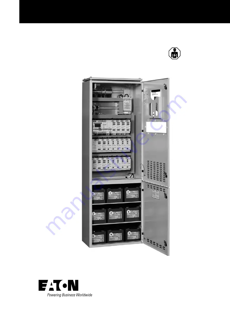
Mounting and Operating Instructions
CEAG Central Battery System ZB-S
Target group, part 1: Qualified electrician acc. to EN 50110-1
Target group. part 2: Electrical instucted persons
CEAG ZB-S
Страница 1: ...Mounting and Operating Instructions CEAG Central Battery System ZB S Target group part 1 Qualified electrician acc to EN 50110 1 Target group part 2 Electrical instucted persons CEAG ZB S...
Страница 2: ...Information regarding these Instructions 4 1 3 Further Applicable Documents 4 1 4 Liability and Guarantee 4 1 5 Copyright Protection 4 1 6 Spare Parts 4 1 7 Recycling 4 2 SAFETY 5 2 1 Inteded Use 5 2...
Страница 3: ...e fuses of the mains and or battery power supply 69 7 5 2 Setting of float charge voltage of the Battery Control Module BCM 69 7 5 3 Checking the fuses of SKU modules 69 7 6 Checking and replacing int...
Страница 4: ...near to the system accessible for every person working with the system and at all times Read the instructions carefully before working on and with the system CEAG Notlichtsysteme GmbH can accept no l...
Страница 5: ...or and control a lighting system with general and emergency lighting Their operation is program controlled They must be programmed and set up by engineers with specialist knowledge of the legal and te...
Страница 6: ...afety Observing the stated safety instructions and regulations can avoid damage to property and people when working with the system However the following organisational measurements must be specified...
Страница 7: ...ase attend to the attachted operating and installation instructions Mains feed in max 50mm Q1 Battery feed in max 50mm Q2 Max 80 circuits max 4 mm X1 1 X2 1 X3 1 X4 1 Marshalling mains max 16mm F10 F1...
Страница 8: ...C please attend to the attached operating and installation instructions Mains feed in max 50mm Q1 Battery feed in max 50mm Q2 Max 68 circuits max 4mm X1 1 X2 1 X3 1 Marshalling mains max 16mm F10 F15...
Страница 9: ...mm X1 1 Z11 Z12 Z21 Z22 Z31 Z32 Z41 Z42 Max 2 5mm flexible with wiring sleeve The final circuits get wired customised Two strands to max 0 5 mm with twin wire end sleeve can be clamped in a clamp spri...
Страница 10: ...pt ambient operation battery 20 C please attend to the attached operating and installation instructions Mains feed in max 16mm X8 Battery feed in max 16mm Q2 Max 40 circuits max 4mm X1 1 X2 1 Marshall...
Страница 11: ...operation 5 C up to 35 C Opt ambient temperature battery 20 C please attend to the attached operating and installation instructions Mains feed in max 16mm X8 Battery feed in max 16mm Q2 Max 40 circui...
Страница 12: ...28 x M32 x 1 5 8 x M32 x 1 5 M40 x 1 5 Datenblatt Anlage Bautiefe Baubreite Bauhoehe Anlagentyp Kabeleinfuehrung Lackierung aussen Schutzart Schutzklasse Gewicht ohne Batterie Tueranschlag Netzanschl...
Страница 13: ...8 x M32 x 1 5 M40 x 1 5 Top view Datenblatt Anlage Bautiefe Baubreite Bauhoehe Anlagentyp Kabeleinfuehrung Lackierung aussen Schutzart Schutzklasse Gewicht ohne Batterie Tueranschlag Netzanschlussspan...
Страница 14: ...35 C Opt ambient temperature battery 20 C please attend to the attached operating and installation instructions Mains feed in max 16mm X8 Battery feed in max 16mm Q2 Max 56 circuits max 4mm X1 1 X2 1...
Страница 15: ...C acc to IEC 486 Duration of emergency lighting 1h 1 5h 2h 3h 8h Recharging time 12 h acc to DIN EN 50171 Ambient temperature operation 5 C up to 35 C Opt ambient temperature battery 20 C please atten...
Страница 16: ...peration 5 C up to 35 C Opt ambient temperature battery 20 C please attend to the attached operating and installation instructions Mains feed in max 16mm X8 Battery feed in max 16mm X9 Max 8 circuits...
Страница 17: ...feed in max 35mm X8 Battery feed in max 35mm X8 Max 80 circuits max 4mm X1 1 X2 1 X3 1 X4 1 X5 1 Addresses optional places DLS 3Ph TLS max 2 5mm customised Connection to ext control switch max 4mm X1...
Страница 18: ...35mm X8 Battery feed in max 35mm X8 Max 80 circuits max 4mm X1 1 X2 1 X3 1 X4 1 X5 1 Addresses optional places DLS 3Ph TLS max 2 5mm customised Connection to ext control switch max 4mm X1 1 S1 S2 Conn...
Страница 19: ...e operation 5 C up to 35 C Mains feed in max 35mm X8 Battery feed in max 35mm X8 Max 50 circuits max 4mm X1 1 X2 1 X3 1 Addresses optional places DLS 3Ph TLS max 2 5mm customised Connection to ext con...
Страница 20: ...up to 35 C Mains feed in max 16mm X8 Battery feed in max 16mm X8 Max 24 circuits max 4mm X1 1 X2 1 Addresses optional places DLS 3Ph TLS max 2 5mm customised Connection to ext control switch max 4mm...
Страница 21: ...hting Recharging time Ambient temperature operation 5 C up to 35 C Mains feed in max 16mm X8 Battery feed in max 16mm X8 Max 20 circuits max 4mm X1 1 X2 1 Addresses optional places DLS 3Ph TLS max 2 5...
Страница 22: ...in a clamp spring terminal 3 17 Data Sheet for US S SOU1 Type of system US S SOU1 Construction Surface mounted plastic distributor housing of thermoplastic with transparent viewing door Height 458 mm...
Страница 23: ...hting Recharging time Ambient temperature operation 5 C up to 35 C Sound level preasure 46dB Mains feed in max 16mm X8 Battery feed in max 16mm X8 Max 26 circuits max 4mm X1 1 X2 1 Addresses optional...
Страница 24: ...max 16mm X8 Battery feed in max 16mm X8 Max circuits max 4mm X1 1 X2 1 Addresses optional places DLS 3Ph TLS max 2 5mm customised Connection to ext control switch max 4mm X1 1 S1 S2 Connection to 24V...
Страница 25: ...on of emergency lighting Recharging time Ambient temperature operation 5 C up to 35 C Sound level preasure 60dB Mains feed in max 16mm X8 Battery feed in max 16mm X8 Max 56 circuits max 4mm X1 1 X2 1...
Страница 26: ...s feed in max 16mm X8 Battery feed in max 16mm X8 Max circuits max 4mm X1 1 X2 1 X3 1 X4x1 Addresses optional places DLS 3Ph TLS max 2 5mm customised Connection to ext control switch max 4mm X1 1 S1 S...
Страница 27: ...stemperatur Betrieb Elek 5 C bis 35 C beachten Sie bitte die beiliegenden Bedienungs und Installationsanweisungen Netzeinspeisung 10 qmm Max 6 Stromkreisabg nge 4 mm 396 230 685 3 24 Data Sheet for US...
Страница 28: ...er 2 Circuit modules23 x SKU Mains circuit breaker Mains distribution box optional Battery circuit breaker Battery distribution box optional Cable infeed from below Charge module CM 1 7 A max 2 module...
Страница 29: ...nfigurations are used depending on the requirements of the site These standardised configurations have names like ZB S 26 or ZB S 18 for operation with up to 26 or 18 SKU CG S modules resp CG with 80...
Страница 30: ...e taken out to a 3 tier installation terminal with tension spring connection s fig on page 28 Free programmable control with a nonvolatile programm memory for programming and user specific parameter s...
Страница 31: ...torage O O Internal with non volatile memory in the CU CG S control module O O External with a memory card reader type of the uses memory card SD card CEAG part no 400 71 347 911 preprogrammed O O SD...
Страница 32: ...med as maintained light Switch on non maintained light Switch on all luminaires circuits which are programmed as non maintained light Ventilator monitor Level triggered by use of a switch 24VDC OK 0V...
Страница 33: ...l The LED lights up when the interal 6V supply voltage is present The Service PIN button is located behind the hole Additional Features O O 24 V external O O 20 W continuous output O O outgoing circui...
Страница 34: ...nection max 0 5 A 24 V AC DC The contact 11 12 is closed in the event of fault The contact 21 22 is closed in the event of an insulation failure The contact 31 32 is closed during boost charging O O T...
Страница 35: ...peak current 250 A max cable diameter 2 5 mm2 with STAR Technology Dimensions and weights approx 0 66 kg H x W X D in mm 170 x 55 x 155 Module width 1 TE 1 and 55mm Item no 400 71 347 051 SKU CG S 1x6...
Страница 36: ...rrent 0 65 A Short circuit current 1500 A Switching cycles 10000 cos phi inductive 0 5 1 0 Environmental conditions Ambient temperature 55 C Protection class IP20 Degree of pollution 2 Distance ventil...
Страница 37: ...ned light and switched maintained light in one circuit by using of CEAG EVGs modules with CG S marking can be programmed without any additional data cable O O Individual monitoring of up to 20 luminai...
Страница 38: ...ight non maintained light and switched maintained light in one circuit by using of CEAG EVGs modules with CG S marking can be programmed without any additional data cable O O Individual monitoring of...
Страница 39: ...ns and battery operation O O Connected rating per circuit 1320W O O Inrush current per circuit 250A ms 1 When the Service Pin is operated the module status is shown as a plain language readout on the...
Страница 40: ...of maintained light non maintained light and switched maintained light in one circuit by using of CEAG EVGs modules with V CG S marking can be programmed without any additional data cable O O Individ...
Страница 41: ...41 4 Construction and Function Mounting and Operating Instructions CEAG Central Battery System ZB S 40071860179 L November 2018 www ceag de...
Страница 42: ...peration of the SWR s Service Pin takes the operator through the following menu structure of the CU CG S control module Additional Features O O Learning current value detection O O Overload display 0...
Страница 43: ...ng of this current deviation has to be entered in the menue 5 3 Monitor mode minimum 15 acc to number of types of luminaires and luminous flux Furthermore the currents have to be measured and saved as...
Страница 44: ...ctric meter per circuit If there is a failure of the external power supply the SWR 150 swiches to battery operation automatically The mains failure gets displayed as mains failure UV at the control un...
Страница 45: ...1860179 L November 2018 www ceag de Battery Address Switched maintained light via external DLS bus module In this switching mode one light switch of the general lighting is scanned and assigned to the...
Страница 46: ...4 9 0 280 105 Table 1 Battery current consumption values A dependent upon number of luminaires and luminous flux ratio LV at 20 C ambient temperature at the luminaire International description T26 Soc...
Страница 47: ...ion TC D Socket G24Q1 G24Q2 Lamp power W 26 18 13 10 Luminous flux ratio 100 71 61 47 100 79 63 48 100 77 63 42 100 68 52 Switch setting 0 3 5 9 0 2 5 9 0 2 4 9 0 4 9 Number of luminaires Current cons...
Страница 48: ...age space on the subrack BGT By default the storage places 7 and 8 on BGT1 are provided for Mains supply of the printer and the communication with the controller CU CG S occur via the rearward contact...
Страница 49: ...e ON Charging fault ON Battery operation ON Mains operation ON Switching capacity of contacts 24V 0 5A AC DC Function of relay contacts 11 12 21 22 31 32 41 42 51 52 No operation ON Failure prior 1 ON...
Страница 50: ...he switch settings depending on the system Switch for loop resistance left ZB S CG 2000 View on the F3 module after opening the front panel Switch setting on the left side for ZB S CG2000 system right...
Страница 51: ...SE O O 2 switching outputs O O Rated current Un 230 V O O Switched current max 10 A 120 A ms Application O O Assembly in the subdistribution board of the monitored circuits due to the low laying effor...
Страница 52: ...he BUS The safety luminaires connected to the emergency lighting system are switched on and off as per the programming The test button triggers a mains emergency light fault on the respective ZB S sys...
Страница 53: ...ible fig 2 Address switch 1 Address switch 2 General lighting Emergency lighting fig 3 Wiring of the CEAG 3 PM IO module CEAG 3 PM IO Modul next Module 3 PM IO TLS TLS ZB S RS485 BUS max 1200 m with J...
Страница 54: ...nitor switch closed 1 kOhm Normal system operation CEAG 3 PM Module NOTES Where several sub distribution boards must be monitored additional devices must be connected and wired with the other devices...
Страница 55: ...55 Technical Data Mounting and Operating Instructions CEAG Central Battery System ZB S 40071860179 L November 2018 www ceag de...
Страница 56: ...Integrated mail client for a comfortable and event based failure notification for up to 5 email addressees Password protected access accounts capable of parametrisation Mounting Pay attention to temp...
Страница 57: ...alogue of the system ZB S ATTENTION BusTopology linear double terminated no spur lines allowed The absolutely essential terminating resistors are included in the control cabinet O O Cable type minimum...
Страница 58: ...ferent 4 1 Battery capacities of more than 126 Ah are reachable with parallel switching of several battery sets 2 Larger capacities on request 3 See CEAG operation instructions for battery cabinets 40...
Страница 59: ...entral Battery System ZB S 40071860179 L November 2018 www ceag de 4 5 Label of ZB S Find the label of the system inside the door The following technical data is given on the label of the system The f...
Страница 60: ...1 32 22 BST Ein On Starkladung Boost Charge Ladest rung Charge Failure Service ISO Fehler ISO Failure ISO Test ISO Test BCM Battery Control Module CM 1 7A DC Charger Module Ein On CCB S2 S1 SKU CG S 2...
Страница 61: ...or Safety Source F1 U 8AT F1 0 8AT F2 U 8AT F2 0 8AT Ein On 1 Fehler Failure 1 Ein On 2 Fehler Failure 2 Service SOU S 2x4A Switching over Unit CLF CLF X X X SEA BSEA B XB1 B2 T1 T1XK1 K1X X N PE L 24...
Страница 62: ...ng points O O The equipment must be handled by persons familiar with the appropriate procedures and signals and able to carry out the handling operations properly and with due regard to safety and haz...
Страница 63: ...plying with chapters 1 2 of these instructions NOTE All connecting cables must be laid according to the rel evant electrical engineering codes of practice and stan dards e g standard series DIN VDE 10...
Страница 64: ...t by specially trained CEAG engineers The installation and connection of the general lighting system is not described in this manual Lighting equipment must be assembled run and connec ted according t...
Страница 65: ...O O Connect the neutral conductor to the terminal block pos 4 O O Connect the L conductors to the terminals on the outgoing feeder pos 2 The mains supply is connected in the control cabinet of the US...
Страница 66: ...its of the SKUs are not offload until the mains supply is isolated Remember that the connecting cables of the battery bank battery cabinet rack may still be live NOTES The connections are accessible w...
Страница 67: ...for connecting a temperature sensor in a ZB S control cabinet 1 ATTENTION For the connection of external temperature sensor an insulated cable must be used Connect the screen with the screen quick co...
Страница 68: ...on of the emergency lighting Maximum pipeline length in the final circuit based on the STAR and CG protocol For a safe communication in the final circuit the line impendaces and pipeline length shown...
Страница 69: ...ers 7 4 Insulation Testing Check that the complete system is isolated and lock it out Do not restore the supply until all work has been completed DANGER Insulation tests may only be carried out betwee...
Страница 70: ...ation When central battery systems are supplied without battery or the type of battery is unknown the tripple charge voltage is set up with the factory default of 245V means 2 27V Z According to the t...
Страница 71: ...initial commissioning and for testing purposes When it is pressed the controller software dis plays addresses and characteristics of the selected mod ule directly on the LC display of the controller...
Страница 72: ...these systems O O Operating and monitoring the system with an F3 module CG controller or building management system BMS O O Software aided system setup using a memory card Operating and monitoring the...
Страница 73: ...rging modules CM 1 7A and CM 3 4A Setting of the max 32 addresses via rotary coding switch 5 10 6 1 address range is implemented by the factory LEDs 7 signal the operating state of the charging module...
Страница 74: ...e O O Test activates a simulated mains failure for testing the emergency lighting equipments while the button is pressed A short button press simulates a 5 second mains failure O O FT activates the me...
Страница 75: ...75 8 Operating Mounting and Operating Instructions CEAG Central Battery System ZB S 40071860179 L November 2018 www ceag de...
Страница 76: ...ease device O O Date Time set O O Automatic FT specify O O Automatic DT specify Previously the substation needs to be found in the menu Main settings Substation setup Before the execution of the comma...
Страница 77: ...time mains return 3 6 Manual reset 3 7 Selective EmgcyOper 3 8 Relay setup 3 9 Buzzer setup 3 10 Display setup 3 11 Charger setup 3 12 Printer setup 3 13 Relay module setup 6 Luminaire setup 6 1 Add...
Страница 78: ...return to Menu 3 with Menu or ESC Line 3 Displays the additional infor mation e g Waiting for SKU data or FT Current value 1 2A ok Menu 1 5 Line 2 Possible status displays Circuit blocked Battery ope...
Страница 79: ...se On Select input field line with Select SKU or circuit with Line 3 shows the current settings of the luminaire addresses 1 20 in the selected circuit Luminaire is off Item 1 Luminaire is on Item 2 L...
Страница 80: ...dress 01 Device name Block device Release device Manual reset Reset deep discharge ok initiates the function The selected stations will be swich ted free and restart operation activated menu Basic set...
Страница 81: ...30 days out of operation the time should be controlled Overview Main menu Test status menu Block reset alarms Basic settings DLS TLS Setup Circuit setup Luminaire setup Logbooksetup Send ServicePinMsg...
Страница 82: ...n the evaluation voltage may also be entered When therefore battery voltage at the end of the limit operating duration is lower than the evaluation voltage a capacity error is displayed If the nominal...
Страница 83: ...vated and de activated with Finish and return to Menu 3 with Menu ok Menu 3 7 Durationtest Delay time mains return Manual reset Selective EmgcyOper etc Note N See also menu option 1 9 Relay status in...
Страница 84: ...iew Main menu Test status menu Block reset alarms Basic settings DLS TLS Setup Circuit setup Luminaire setup Logbooksetup Send ServicePinMsg Menu 3 Language Date time Functiontest Durationtest Delay t...
Страница 85: ...bbon of the printer ok Menu 3 16 Search substation Group no 07 Substation S1 S2 mode Slave S1 S4 mode Menu finishes the entry and the following display appears Device addresse 01 Version Z410C ND 00 0...
Страница 86: ...only one function per key the star icon goes out when a key is assigned another function Select the function key 1 to 3 with keys Highlight the function with Select the function with ok Finish and re...
Страница 87: ...rd activated Password 6 digits Password 123231 Password 1 ok Menu 3 23 Serialnumber type Password protection Daylight saving time Service info This is a display with information about the status of th...
Страница 88: ...on These module names are stored on the memory card and displayed in the LCD display menus as operator help Text assignments cannot be made with the CU CG S if a memory card is not inserted A more use...
Страница 89: ...t new rated value Deactivate SKU Subrack No SKU No Type SKU CG S 2x3 OK key deactivate Overview Main menu Test status menu Block reset alarms Basic settings DLS TLS Setup Circuit setup Luminaire setup...
Страница 90: ...dules Text assignment Monitoring mode DLS TLS Assignment Get new rated value Menu 5 3 ok Text assignments SKU1 8 circuit 2 Type SKU CG S 2x3 Circuit name Menu 5 4 ok Select line 1 2 3 or the input fie...
Страница 91: ...be assigned to complete circuits Menu 5 6 ok On completion of the procedure the CU CG S control module returns to Menu 5 Circuit setup The procedure can be cancelled with the ESC or Menu keys Main scr...
Страница 92: ...tion Menu can cel and return to the previous menu any changes en tered are saved ESC cancel and return to the previous menu any changes en tered are not saved flashing input prompt ok Menu 6 1 SKU 1 8...
Страница 93: ...st status menu Block reset alarms Basic settings DLS TLS Setup Circuit setup Luminaire setup Logbooksetup Send ServicePinMsg Menu 6 Add remove Luminaire search Text assignments DLS TLS Assignment Sele...
Страница 94: ...s the function direct from the main menu Menu ESC returns to the main menu This function is provided for service engineers and has no relevance for normal operation Overview Main menu Test status menu...
Страница 95: ...most common method for suppressing interference is screening 9 1 1 Cable screens Cable screens usually consist of non magnetic materials such as copper or aluminium The most popular screens for cable...
Страница 96: ...all error codes are shown Overview of the failure codes Z571 0 Code Source Failure description Old failures 2 BCM Insulation fault Minus 3 BCM Insulation fault Plus 4 BCM Battery voltage under Minimum...
Страница 97: ...ng on the start duration and end of the work O O Safety measures while the work is being carried out e g standby lighting power supply isolation and lock out e g removing the fuses key operated switch...
Страница 98: ...h results in the substation setup menu 3 Basic settings ok Menu 2 2 This device all devices Device address 01 Device name ok initiates the function All functions are cancelled all outputs will be isol...
Страница 99: ...the top of the switch cabinet The terminal assignment is shown on the schedules on the front of the enclosures for the screw push on terminals on the module and on the terminal blocks for the external...
Страница 100: ...w ceag de Station type ZB S US S Terminal number Type of cable Destination Terminal number Type of cable Destination 1 41 2 42 3 43 4 44 5 45 6 46 7 47 8 48 9 49 10 50 11 51 12 52 13 53 14 54 15 55 16...
Страница 101: ...Battery circuit interrupted Battery capacity too low acc to dura tion test Fan fault detected via Z1 Z4 Transmission fault to charger Battery voltage too high Battery voltage too low Circuit fault X C...
Страница 102: ...te switch or remote indicator for emergency lighting systems Contact assignment C0 14 NO C0 24 NO C0 34 NO C1 44 NO C0 12 NC C0 22 NC C0 32 NC C1 54 NO Note NO normally open NC normally closed The dev...
Страница 103: ...aire 17 Luminaire 7 Switch 1 Switch 1 Switch 2 Switch 2 Luminaire 16 Luminaire 6 Switch 1 Switch 1 Switch 2 Switch 2 Luminaire 15 Luminaire 5 Switch 1 Switch 1 Switch 2 Switch 2 Luminaire 14 Luminaire...
Страница 104: ...DALI controller DALI Bus incl DALI EVG incl DALI EVG incl DALI EVG max 1m V CG SUW Monitoring module with change over unit 230V UV A V CG S 4 400 W Monitoring Module V CG SE 4 400 W Monitoring Module...
Страница 105: ...__________________ Customer No __________________________________ Customer Order No ____________________________ Customer signature ____________________________________________________________________...
Страница 106: ...ndo se disponga a manipular las bater as desconecte totalmente la corriente el ctrica aseg rese de que no se pueden volver a conec tar y compruebe que no tengan corriente No desconecte la bater a con...
Страница 107: ...baterias atrav s dos polos Em caso de substitui o utilize apenas pe as sobressalentes originais Rom n Instruc iuni generale de siguran Bateriile nu sunt destinate pentru uz personal Instalareatrebuie...
Страница 108: ...rlos un electricista cualificado de acuerdo con la normativa de seguridad y prevenci n de accidentes Los dispositivos deben utilizarse de acuerdo con su uso previsto en buen estado y sin da os Retire...
Страница 109: ...idade completamente certifique se de que n o pode ser ligada e verifique se n o existe tens o O supramencionado aplica se rede el trica energia de reserva e poss vel tens o de controlo e externa N o d...
Страница 110: ...110 Notes Mounting and Operating Instructions CEAG Central Battery System ZB S 40071860179 L November 2018 www ceag de Notes...
Страница 111: ...111 Notes Mounting and Operating Instructions CEAG Central Battery System ZB S 40071860179 L November 2018 www ceag de Notes...
Страница 112: ...e property of their respective owners At Eaton we re energized by the challenge of powering a world that demands more With over 100 years experience in electrical power management we have the expertis...