


2
Instruction Booklet
IB020004EN
Effective October 2020
Instructions for installation and maintenance
of the AMPGARD Reduced Voltage Soft Starter
EATON
www.eaton.com
m
DANGER
HAZARDOUS VOLTAGE
ALL POWER SOURCES MUST BE ISOLATED AND LOCKED OUT BEFORE
SERVICING THE EQUIPMENT
READ AND UNDERSTAND THESE INSTRUCTIONS IN THEIR ENTIRETY
BEFORE INSTALLING, OR MAINTAINING THIS EQUIPMENT. ONLY
QUALIFIED PERSONS SHOULD INSTALL, MAINTAIN, ADJUST, OR REPAIR
THESE UNITS. A QUALIFIED PERSON IS ONE WHO IS FAMILIAR WITH THE
CONSTRUCTION AND OPERATION OF THE EQUIPMENT AND THE HAZARDS
ASSOCIATED WITH IT.
Purpose
To ensure the safe and successful installation and maintenance of
the AMPGARD Reduced Voltage Soft Starter (RVSS). This equip-
ment may be installed as an individual structure or may be part of a
lineup of AMPGARD products.
1. Introduction
1.1 Basic description of a single unit
The AMPGARD RVSS is designed to start medium voltage motors
at reduced voltages with specific ramp times and amperages. An
individual unit consists of a standard structure that is 36 inches wide
by 30 inches deep by 92 inches tall, including the main bus. The top
half is referred to as the upper cell and the bottom half as the lower
cell (see
Figure 1
).
Figure 1. AMPGARD RVSS.
1.2 Upper cell
The upper cell consists of a full voltage starter with a non-load
break isolation switch, medium voltage current limiting fuses, an
SL Main contactor, and current transformers (see
Figure 2
). A low
voltage control compartment is located on the front of the controller
medium voltage door. Refer to IB48041 (Instructions for AMPGARD
400 ampere medium voltage starter) for operating and maintenance
instructions on the upper cell.
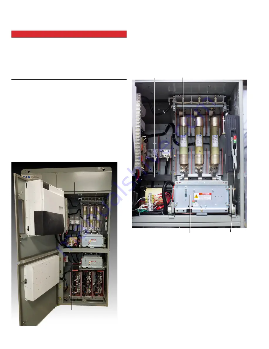
Figure 2. Upper cell.
Main fuses
Main contactor
Isolation switch
handle mechanism
Current transformer
Upper cell
Lower cell


