13
Instruction Booklet
IB020004EN
Effective October 2020
Instructions for installation and maintenance
of the AMPGARD Reduced Voltage Soft Starter
EATON
www.eaton.com
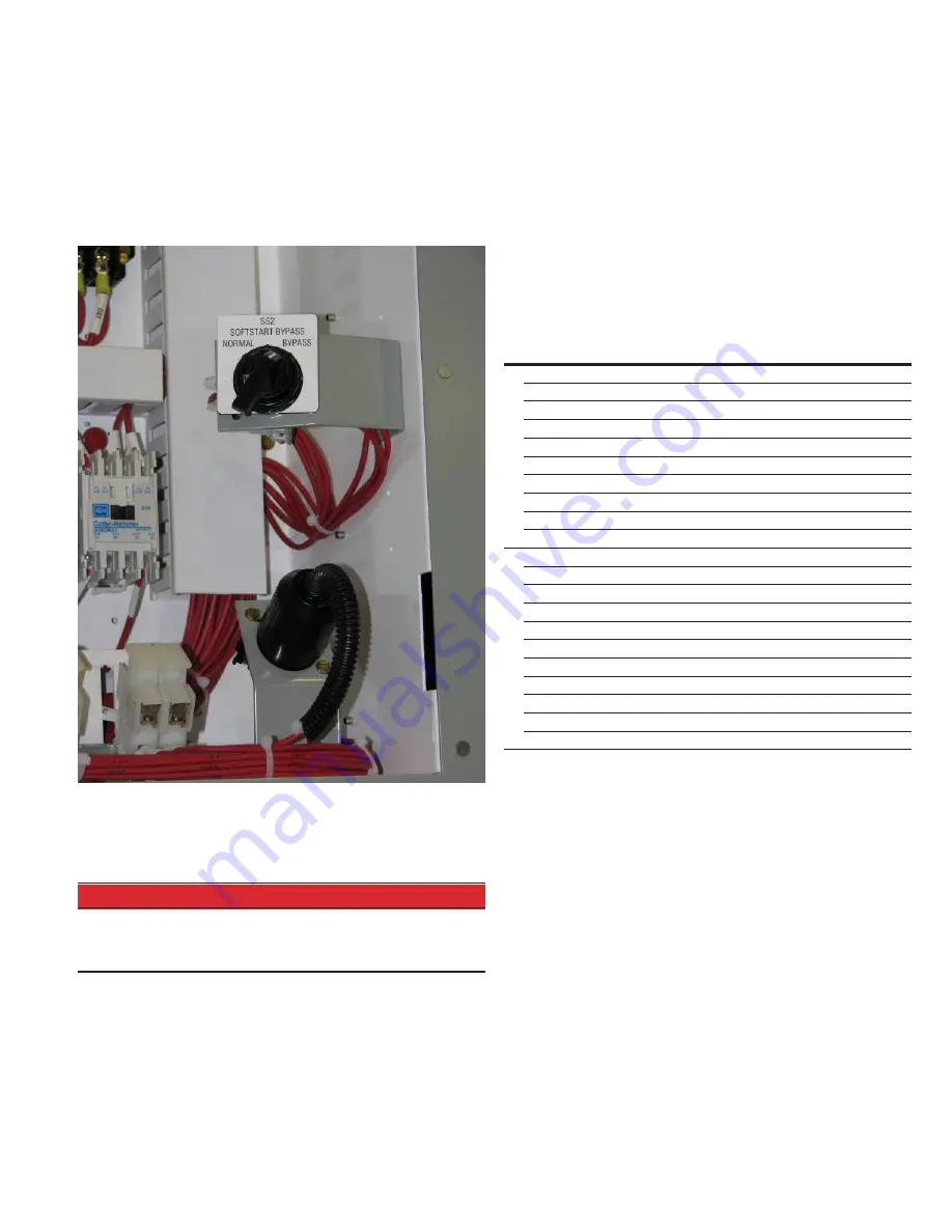
3.3 Emergency bypass mode
In case of emergency, the starter can be used as a full voltage
starter. Turn the SS2 SOFTSTART BYPASS switch located in the low
voltage compartment of the upper section to bypass. If power is
applied, you should hear the Bypass contactor close immediately on
operation of the SS2 switch. The solid-state truck is now bypassed
and the unit will start directly across the line as soon as the Main
contactor is closed from a start command (see
Figure 24
below.)
Figure 24.
Since the Bypass contactor is separate from the solid-state truck
assembly on this model, no medium voltage cabling needs to be
moved to allow running with the truck removed for service or repair.
m
DANGER
HIGH VOLTAGE FROM RC SNUBBER STORED ENERGY MAY BE PRESENT
AFTER DISCONNECTING POWER TO THE UNIT. WAIT AT LEAST 15 MIN-
UTES BEFORE MAKING CONTACT WITH RVSS POWER POLES TO ALLOW
FOR PROPER VOLTAGE DISCHARGE.
To run with the truck removed: Isolate all power sources and allow
15 minutes for everything to discharge. Follow instructions in Section
2.1 for truck removal. Ensure that the 48V control power wires and
fibers are secured safely back out of the way while the truck is
out. Close all enclosure doors and restore power. After power is
restored, change the SS2 SOFTSTART BYPASS switch to “BYPASS”.
3.4 Maintenance
Please refer to section 3.1 for additional information regarding main-
tenance of AMPGARD and SL contactor. This section will address
some of the more specific features of the RVSS product.
In general, fastener torque will follow standard AMPGARD specifica-
tions shown in
Table 1
. More specific requirements for the SL
contactor can be found in IB48018N. Due to the highly precise
nature required in the SCR pole construction, the internal compo-
nents of the solid-state truck assembly are not intended to be
field-serviceable. Should the RVSS truck have a component fail, it is
recommended that the corresponding full phase pole be replaced.
(See Section 2.1 for removal and replacement procedure.)
Table 1.
Bolt size
dia-thread
Steel
grade 2
18 - 8
St. St.
Brass
Silicone
bronze
316
St. St.
Steel
grade 5
Inc
h
-lb
s.
2 - 56
1 - 2
1 - 2
0.75 - 1
1 - 2
1 - 2
-
3 - 48
2-3
2-3
1.50 - 3
2-3
2-3
-
4 - 40
3-4
3-4
2-3
2-4
3-5
-
5 - 40
5-7
4-7
3-4
4-6
5-7
-
6 - 32
6-8
6-9
4-5
5-8
6-9
-
8 - 32
11 - 15
12 - 16
7-9
10 -14
12 - 16
-
10 - 24
16 - 22
14 - 18
9 - 13
12 - 16
15 - 19
-
10 - 32
18 - 25
17 - 25
11 - 15
16 - 23
18 - 26
-
1/4 - 20
37 - 53
36 - 60
22 - 32
36 - 60
48 - 72
57 - 81
1/4 - 28
42 - 60
-
25 - 36
-
-
65 - 93
F
o
o
t-
lb
s.
5/16 - 18 7-9
7-9
4-5
9 - 13
8 - 11
10 - 14
3/8 - 16
12 - 16
12 - 16
7 - 10
14 - 19
12 - 17
18 - 28
7/16 - 14 19 - 26
17 - 25
11 - 15
25 - 35
18 - 25
28 - 40
1/ 2 - 13 28 - 39
30 - 45
16 - 23
40 - 50
30 - 45
42 - 60
9/16 - 12 40 - 56
50 - 60
24 - 34
55 - 70
50 - 70
61 - 87
5/8 - 11
55 - 78
50 - 75
33 - 47
75 - 95
55 - 80
84 - 120
3/4 - 10
97 - 138
70 - 100
58 - 83
140 -170
75 - 105
150 - 213
3/4 - 16
108 - 154 -
64 - 92
-
-
167 - 238
7/8 - 9
94 - 133
105 - 155 93 - 133
240 - 270 110 - 160 240 - 343
1 - 8
140 - 200 160 - 230 140 - 200 310 - 395 165 - 235 360 - 515
1 - 14
157 - 224 -
157 - 224 -
-
405 - 578


