background image

4

Instruction Booklet 

IB020004EN

Effective October 2020

Instructions for installation and maintenance 

of the AMPGARD Reduced Voltage Soft Starter 


EATON

 www.eaton.com

The control system for the RVSS is located in this low voltage 

compartment.  Components include the DSP control board, IOB 

input-output interface board, C445 BCM Base Control Module and 

MUI Monitoring User Interface (see 

Figure 5

 and 

Figure 6

).

Figure 6. Control system boards.

1.4 RVSS truck

The RVSS power poles are mounted on an easy to remove, roll out 

truck assembly.  Additionally, each pole is individually removable and 

replaceable without extracting the rest of the truck assembly. (see 

Figure 7

).

Figure 7. RVSS truck.

2. Installation

Refer to IB48041 (Instructions for AMPGARD 400 ampere medium 

voltage starter) for installation instructions.  During installation, 

the RVSS truck may be removed by following the instructions in 

Section 2.1.  Truck removal provides easy access to the cable area in 

the lower cell for bottom entry starters and is required if dielectric 

testing of the starter assembly is to be performed.  To remove the 

RVSS truck utilizing the provided ramp, a minimum clearance of 60 

inches is required in front of the starter.  

CAUTION

TO PREVENT DAMAGE TO THE RVSS, REMOVE THE RVSS TRUCK 

INCLUDING ANY INPUT OR OUTPUT MV CONNECTIONS BEFORE  

PERFORMING MEGGER/HIPOT TESTING. 

2.1 RVSS truck removal

DANGER

HIGH VOLTAGE FROM RC SNUBBER STORED ENERGY MAY BE PRESENT 

AFTER DISCONNECTING POWER TO THE UNIT.  WAIT AT LEAST 15 MIN-

UTES BEFORE MAKING CONTACT WITH RVSS POWER POLES TO ALLOW 

FOR PROPER VOLTAGE DISCHARGE.  

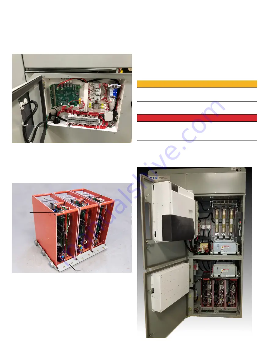
1.  Ensure the starter is de-energized by opening the isolation 

switch and LOTO the feeder.  Open the medium voltage doors 

on the upper and lower cells (see 

Figure 8

).  (See IB48041 for 

more information.)

Figure 8. 

RVSS power poles

Bypass contactor

Pull bar

Pole hold-down plate

Содержание AMPGARD RVSS

Страница 1: ...3 General notes and maintenance 9 3 1 Additional reference documents 9 3 2 Standard drawings and dimensions 10 3 3 Emergency bypass mode 13 3 4 Maintenance 13 3 5 Support services 14 Read and underst...

Страница 2: ...PGARD products 1 Introduction 1 1 Basic description of a single unit The AMPGARD RVSS is designed to start medium voltage motors at reduced voltages with specific ramp times and amperages An individua...

Страница 3: ...al relay used to provide motor protection while running on Bypass Figure 3 Low voltage components 1 3 Lower cell The lower cell consists of a welded frame with an upper tray for the Bypass contactor a...

Страница 4: ...RVSS truck may be removed by following the instructions in Section 2 1 Truck removal provides easy access to the cable area in the lower cell for bottom entry starters and is required if dielectric t...

Страница 5: ...CB and the 48VDC power plug before removing the phase leg assembly Leave the five front facing fiber optic connectors in place 3 Undo the hook and loop straps fastening the fibers and power wires to t...

Страница 6: ...ER TO ACCOMMODATE THE RAMP AND TRUCK TRUCK APPROXIMATE WEIGHT IS 260 LBS ONCE THE TRUCK DESCENT DOWN THE RAMP BEGINS THE TRUCK SPEED INCREASES RAPIDLY 6 The truck is now ready to be removed Grasping...

Страница 7: ...ation 1 Place the ramp in front of the starter Place the truck in front of the ramp aligning the wheels inside the ramp s outside flanges With both hands on the side sheets at the front of the truck p...

Страница 8: ...power supply wires to the fanout board power sockets on each pole Strap fiber and 48V power supply wire harness back down to the truck using the hook loop straps 2 4 RVSS structure transport lifting F...

Страница 9: ...LL SAFETY REGULATIONS WHILE LIFTING MOVING STRUCTURE INTO PLACE 3 General notes and maintenance m DANGER HIGH VOLTAGE FROM RC SNUBBER STORED ENERGY MAY BE PRESENT AFTER DISCONNECTING POWER TO THE UNIT...

Страница 10: ...ooklet IB020004EN Effective October 2020 Instructions for installation and maintenance of the AMPGARD Reduced Voltage Soft Starter EATON www eaton com 3 2 Standard drawings and dimensions Figure 21 Ty...

Страница 11: ...struction Booklet IB020004EN Effective October 2020 Instructions for installation and maintenance of the AMPGARD Reduced Voltage Soft Starter EATON www eaton com Figure 22 AMPGARD RVSS typical schemat...

Страница 12: ...struction Booklet IB020004EN Effective October 2020 Instructions for installation and maintenance of the AMPGARD Reduced Voltage Soft Starter EATON www eaton com Figure 23 AMPGARD RVSS typical schemat...

Страница 13: ...TSTART BYPASS switch to BYPASS 3 4 Maintenance Please refer to section 3 1 for additional information regarding main tenance of AMPGARD and SL contactor This section will address some of the more spec...

Страница 14: ...butor for product pricing availabil ity ordering expediting and repairs Website Use the Eaton website to find product information You can also find information on local distributors or Eaton s sales o...

Страница 15: ...15 Instruction Booklet IB020004EN Effective October 2020 Instructions for installation and maintenance of the AMPGARD Reduced Voltage Soft Starter EATON www eaton com Notes...

Страница 16: ...contractual agreement between Eaton and the purchaser THERE ARE NO UNDERSTANDINGS AGREEMENTS WARRANTIES EXPRESSED OR IMPLIED INCLUDING WARRANTIES OF FITNESS FOR A PARTICULAR PURPOSE OR MERCHANTABILIT...

Отзывы: