


UPS System Installation
4-8
Eaton 9E UPS (20–30 kVA, 208/220V) Generation 3 Installation and Operation Manual P-164000301—Rev 1
www.eaton.com/powerquality
4.6
Sidecar Integrated Accessory Cabinet-Bypass
If installing an SIAC-B, refer to the
Eaton 9E Sidecar Integrated Accessory Cabinet-Bypass Installation and
Operation Manual
listed in paragraph 1.7 for installation instructions.
After the SIAC-B is installed, proceed to paragraph 4.9 if installing Integrated Accessory Cabinet-Distribution;
otherwise, proceed to paragraph 4.10 to complete the wiring of the UPS.
4.7
Integrated Accessory Cabinet-Tie
If installing an IAC-T, refer to the
Eaton 9E Integrated Accessory Cabinet-Tie and Bypass Installation and
Operation Manual
listed in paragraph 1.7 for installation instructions.
After the IAC-T is installed, proceed to paragraph 4.9 if installing Integrated Accessory Cabinet-Distribution;
otherwise, proceed to paragraph 4.10 to complete the wiring of the UPS.
4.8
Integrated Accessory Cabinet-Tie and Bypass
If installing an IAC-TB, refer to the
Eaton 9E Integrated Accessory Cabinet-Tie and Bypass Installation and
Operation Manual
listed in paragraph 1.7 for installation instructions.
After the IAC-TB is installed, proceed to paragraph 4.9 if installing Integrated Accessory Cabinet-Distribution;
otherwise, proceed to paragraph 4.10 to complete the wiring of the UPS.
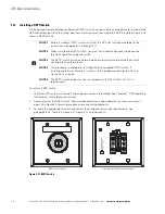
4.9
Integrated Accessory Cabinet-Distribution
If installing IAC-D, refer to the
Eaton 9E Integrated Accessory Cabinet-Distribution Installation and Operation
Manual
listed in paragraph 1.7 for installation instructions.
After the IAC-D is installed, proceed to paragraph 4.10 to complete the wiring of the UPS.
4.10
External Power Wiring Installation
To install wiring:
1.
Install conduit for UPS input and output wiring.
2.
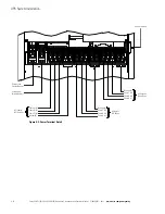
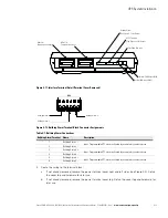
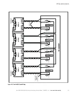
Route the wiring to the UPS terminal blocks on the back of the UPS. See Figure 4-6 for wiring access
information and Figure 4-7 for terminal locations.
3.
Connect phase A, B, C, and Neutral rectifier input power wiring from the utility source to the rectifier input
and neutral terminals. See paragraph 3.2.2 for wiring and termination requirements.
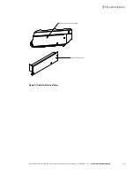
For a detailed view of the UPS terminal block, see Figure 4-8.
4.
If wiring a dual-feed system, proceed to Step 5; otherwise, proceed to Step 6.
5.
Connect phase A, B, and C, and Neutral bypass input power wiring from the utility source to the bypass
input terminals and neutral terminals. See paragraph 3.2.2 for wiring and termination requirements.
For a detailed view of the UPS terminal block, see Figure 4-8.
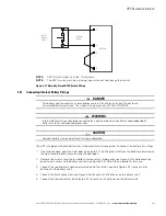
6.
Connect phase A, B, and C, and Neutral (if required) power wiring from output terminals and neutral
terminals to the critical load. See paragraph 3.2.2 for wiring and termination requirements.
For a detailed view of the UPS terminal block, see Figure 4-8.
NOTE
Without accessory cabinets, conduit and wiring enter from the bottom of the UPS
conduit landing plate. With accessory cabinets, wiring can be installed between the
UPS and accessory cabinets by using conduit or by routing wiring through the
power terminal cover base wiring channels.
Содержание 9E
Страница 1: ...Eaton 9E UPS 20 30 kVA 208 220V Generation 3 Installation and Operation Manual ...
Страница 2: ......
Страница 3: ...Eaton 9E UPS 20 30 kVA 208 220V Generation 3 Installation and Operation Manual ...
Страница 21: ...Section 1 Installation ...
Страница 22: ......
Страница 65: ...Section 2 Operation ...
Страница 66: ......
Страница 113: ......
Страница 114: ... P 164000301 1 P 164000301 1 ...


