Installation
4-24
Eaton 93E Integrated Transformer Cabinet (ITC) Installation Manual P-164000074—Rev 3
www.eaton.com/powerquality
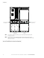
19. Route the UPS rectifier and bypass input wiring (phase A, B, and C, Neutral and Ground) from ITC1 and
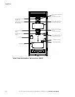
ITC2 through the wire tray and the power terminal cover base wiring channels (see Figure 4-16) on the
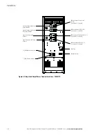
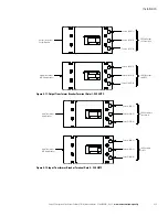
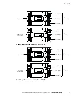
back of the ITC to the UPS terminal block on the back of the UPS. See Figure 4-10 or Figure 4-13 for ITC
terminal locations. See paragraph 3.2.2, Table 3-4, and Table 3-5 for ITC wiring and termination
requirements. Refer to the applicable Eaton 93E UPS Installation and Operation manual listed in paragraph
1.6 for their respective terminal locations and termination requirements.
20. Connect phase A, B, C, Neutral, and Ground rectifier input power wiring from the ITC1 to the UPS rectifier
input, neutral, and ground terminals. See paragraph 3.2.2 for wiring and termination requirements.
21. Connect phase A, B, C, Neutral, and Ground ITC output power wiring to the ITC1 AC output to UPS,
neutral, and ground terminals. See paragraph 3.2.2 for wiring and termination requirements.
22. Connect phase A, B, C, Neutral, and Ground bypass input power wiring from the ITC2 to the UPS bypass
input, neutral, and ground terminals. See paragraph 3.2.2 for wiring and termination requirements.
23. Connect phase A, B, C, Neutral, and Ground ITC2 output power wiring to the ITC2 AC output to UPS,
neutral, and ground terminals. See paragraph 3.2.2 for wiring and termination requirements.
24. Secure the power cables to the power terminal cover base using wire ties after all electrical connections
have been completed.
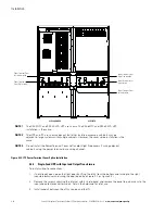
25. Install the power terminal cover tops using the provided hardware (see Figure 4-18).
26. Install the ITC left side power terminal cover and the UPS right side power terminal cover using the
provided hardware (see Figure 4-18).
27. Install the splice cover using the provided hardware (see Figure 4-18).
28. Reinstall the internal safety shield panel removed in Step 2.
29. Close the outside door and secure the latch.
30. After the ITC is installed and wired, return to the applicable Eaton 93E UPS Installation and Operation
manual listed in paragraph 1.6 to complete the UPS wiring.
4.4.4
Dual-Feed UPS with Two Input Transformers and One Output Transformer
To install wiring to connections:
1.
If not already open, open the front door by lifting the latch from the bottom and turning to the right
(counterclockwise) and swing the door open (see Figure 4-1 or Figure 4-4).
2.
Remove the screws securing the internal safety shield panel and remove the panel to gain access to the
input and output breaker terminals. Retain the hardware for later use.
3.
Install conduit between the utility sources and ITC1 and ITC2.
4.
Route the AC utility source input wiring (phase A, B, and C, and Ground) through the conduit and the wire
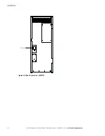
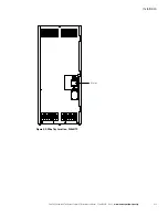
tray (Figure 4-8 or Figure 4-9) on the back of the ITC1 to the ITC AC input to transformer terminals. See
Figure 4-10 or Figure 4-13 for ITC terminal locations. See paragraph 3.2.2, Table 3-4, and Table 3-5 for ITC
wiring and termination requirements.
5.
Connect phase A, B, C, and ground ITC1 input power wiring from the utility source to the ITC AC input to
transformer terminals and ground terminals. See paragraph 3.2.2 for wiring and termination requirements.
6.
Route the AC utility source input wiring (phase A, B, and C, and Ground) through the conduit and the wire
tray (Figure 4-8 or Figure 4-9) on the back of the ITC2 to the ITC AC input to transformer terminals. See
Figure 4-10 or Figure 4-13 for ITC terminal locations. See paragraph 3.2.2, Table 3-4, and Table 3-5 for ITC
wiring and termination requirements.
7.
Connect phase A, B, C, and ground ITC2 input power wiring from the utility source to the ITC AC input to
transformer terminals and ground terminals. See paragraph 3.2.2 for wiring and termination requirements.
Содержание 93E 30ITC
Страница 1: ...Eaton 93E Integrated Transformer Cabinet 30ITC and 60ITC Installation Manual ...
Страница 2: ......
Страница 3: ...Eaton 93E Integrated Transformer Cabinet 30ITC and 60ITC Installation Manual ...
Страница 73: ......
Страница 74: ... P 164000074 3 P 164000074 3 ...

