Installation
4-10
Eaton 93E Integrated Transformer Cabinet (ITC) Installation Manual P-164000074—Rev 3
www.eaton.com/powerquality
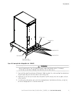
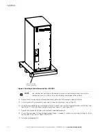
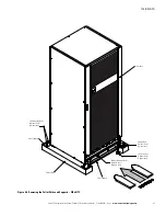
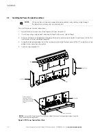
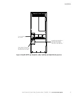
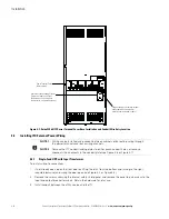
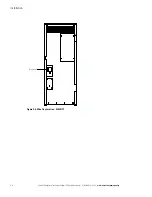
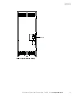
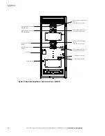
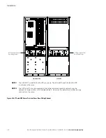
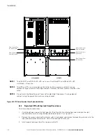
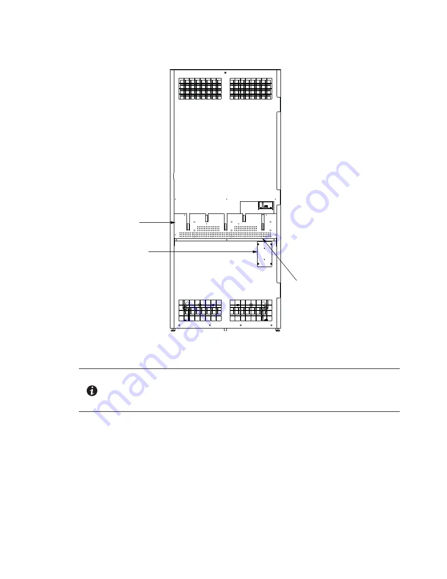
Figure 4-7. Eaton 93E 60ITC Power Terminal Cover Base Installation and Conduit Wire Entry Location
4.4
Installing ITC External Power Wiring
4.4.1
Single-Feed UPS with Input Transformer
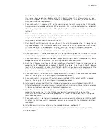
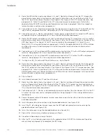
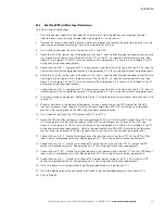
To install wiring to connections:
1.
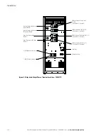
If not already open, open the front door by lifting the latch from the bottom and turning to the right
(counterclockwise) and swing the door open (see Figure 4-1 or Figure 4-4).
2.
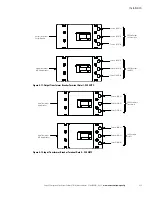
Remove the screws securing the internal safety shield panel and remove the panel to gain access to the
input and output breaker terminals. Retain the hardware for later use.
3.
Install conduit between the utility source and the ITC.
Alternate Conduit Landing Plate for
Transformer Input and Output
(Remove panel to drill or punch
conduit holes, or remove knockouts.)
Conduit Landing for Transformer Input
and Output when using conduit
(Install conduit to bottom of base.)
Power Terminal Cover
Base Installed
NOTE 1
Wiring can be installed using conduit between cabinets or by routing wiring through
the power terminal cover base wiring channels.
NOTE 2
Remove the ITC conduit landing plates to drill or punch conduit holes, or remove
knockouts the knockouts in the conduit plate (see Figure 4-6 or Figure 4-7).
Содержание 93E 30ITC
Страница 1: ...Eaton 93E Integrated Transformer Cabinet 30ITC and 60ITC Installation Manual ...
Страница 2: ......
Страница 3: ...Eaton 93E Integrated Transformer Cabinet 30ITC and 60ITC Installation Manual ...
Страница 73: ......
Страница 74: ... P 164000074 3 P 164000074 3 ...


