background image

Installation Plan and Unpacking

3-6

Eaton 93E Integrated Transformer Cabinet (ITC) Installation Manual P-164000074—Rev 3

 www.eaton.com/powerquality

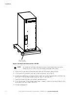
Figure 3-4. 93E 60ITC Cabinet Dimensions (Front, Right Side, and Rear Views)

Dimensions are in millimeters [inches]

Содержание 93E 30ITC

Страница 1: ...Eaton 93E Integrated Transformer Cabinet 30ITC and 60ITC Installation Manual ...

Страница 2: ......

Страница 3: ...Eaton 93E Integrated Transformer Cabinet 30ITC and 60ITC Installation Manual ...

Страница 4: ...allation et de maintenance des batteries et de l onduleur Veuillez consulter entièrement ces instructions avant de faire fonctionner l équipement et conserver ce manuel afin de pouvoir vous y reporter ultérieurement Eaton is a registered trademarks of Eaton Corporation or its subsidiaries and affiliates National Electrical Code and NEC are registered trademarks of National Fire Protection Associat...

Страница 5: ...ATION 4 1 4 1 Preliminary Installation Information 4 1 4 2 Unloading the ITC from the Pallet 4 1 4 2 1 Unloading the 30ITC 4 1 4 2 2 Unloading the 60ITC 4 5 4 3 Installing the Power Terminal Cover Base 4 8 4 4 Installing ITC External Power Wiring 4 10 4 4 1 Single Feed UPS with Input Transformer 4 10 4 4 2 Single Feed UPS with Input and Output Transformers 4 20 4 4 3 Dual Feed UPS with Two Input T...

Страница 6: ... ITC Installation Manual P 164000074 Rev 3 www eaton com powerquality 7 PRODUCT SPECIFICATIONS 7 1 7 1 Model Numbers 7 1 7 2 Specifications 7 1 7 2 1 Input Transformer 7 1 7 2 2 Output Transformer 7 1 7 2 3 Environmental and Safety Specifications 7 2 WARRANTY W 1 ...

Страница 7: ...the Pallet Skids and Supports 93E 60ITC 4 7 Figure 4 5 ITC Power Terminal Cover Parts 4 8 Figure 4 6 Eaton 93E 30ITC Power Terminal Cover Base Installation and Conduit Wire Entry Location 4 9 Figure 4 7 Eaton 93E 60ITC Power Terminal Cover Base Installation and Conduit Wire Entry Location 4 10 Figure 4 8 Wire Tray Location 93E 30ITC 4 12 Figure 4 9 Wire Tray Location 93E 60ITC 4 13 Figure 4 10 Inp...

Страница 8: ...List of Figures iv Eaton 93E Integrated Transformer Cabinet ITC Installation Manual P 164000074 Rev 3 www eaton com powerquality This page intentionally left blank ...

Страница 9: ...60ITC Single Transformer 3 10 Table 3 5 External Power Wiring Requirements for the Eaton 93E 30ITC and 93E 60ITC Dual Transformer 3 11 Table 3 6 External Input Power Cable Terminations for the Eaton 93E 30ITC Single Transformer 3 12 Table 3 7 External Input Power Cable Terminations for the Eaton 93E 30ITC Dual Transformer 3 12 Table 3 8 External Input Power Cable Terminations for the Eaton 93E 60I...

Страница 10: ...List of Tables vi Eaton 93E Integrated Transformer Cabinet ITC Installation Manual P 164000074 Rev 3 www eaton com powerquality This page intentionally left blank ...

Страница 11: ...former provides an isolated output to the critical load or for applications that require 480 Vac To save space the transformer is contained in the same ITC as the input transformer The ITC is housed in a single free standing cabinet with a safety shield behind the door for hazardous voltage protection The cabinets match the UPS cabinet in style and color Figure 1 1 shows the Eaton 93E 30ITC and Ea...

Страница 12: ... and match ITC is installed adjacent to the UPS or other accessory cabinet The recommended installation location is to the left of the UPS cabinet See Figure 1 2 and Figure 1 3 for line up and match configuration views 1 2 Model Configurations The following model configurations are available l 93E 30ITC for use with the 93E 30 kVA UPS Single Transformer Cabinet Contains a three phase 480 Vac to 20...

Страница 13: ...rated Transformer Cabinet ITC Installation Manual P 164000074 Rev 3 www eaton com powerquality 1 3 Figure 1 2 Eaton 93E 30 kVA UPS and Eaton 93E 30ITC Figure 1 3 Eaton 93E 60 kVA UPS and Eaton 93E 60ITC UPS 93E 30ITC UPS 93E 60ITC ...

Страница 14: ...accessories installed The term line up and match refers to accessory cabinets that are physically located adjacent to the UPS The term standalone refers to accessory cabinets that are located separate from the UPS 1 5 Symbols Controls and Indicators The following are examples of symbols used on the UPS or accessories to alert you to important information Icon Description NOTE Information notes cal...

Страница 15: ...r installation wiring and safety information and detailed illustrations of cabinets with dimensional and connection point drawings Refer to the Eaton 93E Integrated Accessory Cabinet Tie and Bypass Installation and Operation Manual for the following additional information l Operation including breakers standard features and optional accessories procedures for using the bypass functions and informa...

Страница 16: ...Introduction 1 6 Eaton 93E Integrated Transformer Cabinet ITC Installation Manual P 164000074 Rev 3 www eaton com powerquality This page intentionally left blank ...

Страница 17: ...exceed 30 C 86 F Do not operate near water or excessive humidity 95 maximum The system is not intended for outdoor use l As a result of the connected loads high leakage current is possible Connection to earth ground is required for safety and proper product operation Do not check UPS system operation by any action that includes removal of the earth ground connection with loads attached l Ensure al...

Страница 18: ...Safety Warnings 2 2 Eaton 93E Integrated Transformer Cabinet ITC Installation Manual P 164000074 Rev 3 www eaton com powerquality This page intentionally left blank ...

Страница 19: ...perate at peak efficiency the installation site should meet the environmental parameters outlined in this manual If the UPS system is to be operated at an altitude higher than 1500m 5000 ft contact an Eaton service representative for important information about high altitude operation The operating environment must meet the weight clearance and environmental requirements specified for the applicab...

Страница 20: ...50 551 225 496 8 at 28 62 Eaton 93E 30ITC with Input and Output Transformer 403 889 378 834 8 at 47 104 Eaton 93E 60ITC with Input Transformer 450 993 416 918 12 at 35 77 Eaton 93E 60ITC with Input and Output Transformer 690 1521 656 1446 12 at 54 120 Table 3 2 ITC Clearances From Top of Cabinet 304 8 mm 12 working space From Front of Cabinet 914 4 mm 36 working space From Back of Cabinet 914 4 mm...

Страница 21: ...cking Eaton 93E Integrated Transformer Cabinet ITC Installation Manual P 164000074 Rev 3 www eaton com powerquality 3 3 Figure 3 1 93E 30ITC Cabinet Dimensions Front Right Side and Rear Views Dimensions are in millimeters inches ...

Страница 22: ... and Unpacking 3 4 Eaton 93E Integrated Transformer Cabinet ITC Installation Manual P 164000074 Rev 3 www eaton com powerquality Figure 3 2 93E 30ITC Dimensions Top and Bottom Views Dimensions are in millimeters inches ...

Страница 23: ...t ITC Installation Manual P 164000074 Rev 3 www eaton com powerquality 3 5 Figure 3 3 93E 30ITC Center of Gravity Dimensions are in millimeters inches Center of Gravity A B C Single Transformer 425 16 7 416 16 4 280 11 0 Dual Transformer 675 26 6 416 16 4 270 10 6 CG B A C ...

Страница 24: ...cking 3 6 Eaton 93E Integrated Transformer Cabinet ITC Installation Manual P 164000074 Rev 3 www eaton com powerquality Figure 3 4 93E 60ITC Cabinet Dimensions Front Right Side and Rear Views Dimensions are in millimeters inches ...

Страница 25: ... and Unpacking Eaton 93E Integrated Transformer Cabinet ITC Installation Manual P 164000074 Rev 3 www eaton com powerquality 3 7 Figure 3 5 93E 60ITC Dimensions Top and Bottom Views Dimensions are in millimeters inches ...

Страница 26: ...inet ITC Installation Manual P 164000074 Rev 3 www eaton com powerquality Figure 3 6 93E 60ITC Center of Gravity Dimensions are in millimeters inches Center of Gravity A B C Single Transformer 515 2 3 416 16 4 397 15 6 Dual Transformer 800 31 5 416 16 4 397 15 6 B CG B C A ...

Страница 27: ...ties are chosen from Table 310 16 of the National Electrical Code NEC Specification is for copper wire with a 90 C rating l Refer to NEC Article 250 and local codes for proper grounding practices l Per NEC Article 300 20 a all three phase conductors must be run in the same conduit Neutral and ground must be run in the same conduit as the phase conductors l Phase rotation must be clockwise starting...

Страница 28: ...ting 60 Hz kVA 30 60 Input Output Voltage Volts 480 208 480 208 480 Vac Input to Input Transformer 3 Phases 1 Ground A Maximum Amps 43 85 Minimum Conductor Size Phase A B and C Number per Phase AWG or kcmil each 6 1 2 1 208 Vac Output from Input Transformer to UPS 3 Phases 1 Neutral 1 Ground B Maximum Amps 96 192 Minimum Conductor Size Phase A B and C Number per Phase AWG or kcmil each 1 0 1 250 1...

Страница 29: ...mum Amps 96 192 Minimum Conductor Size Phase A B and C Number per Phase AWG or kcmil each 1 0 1 250 1 Minimum Conductor Size Neutral Number per Phase AWG or kcmil each 1 0 2 250 2 208 Vac Input to Output Transformer from UPS 3 Phases 1 Ground C Maximum Amps 83 167 Minimum Conductor Size Phase A B and C Number per Phase AWG or kcmil each 1 0 1 250 1 480 Vac Output from Output Transformer to Critica...

Страница 30: ...tral 2 6 250 22 6 200 1 4 Hex Building Load and Inter cabinet Ground TBG Ground 3 14 1 0 5 1 45 Slotted Table 3 7 External Input Power Cable Terminations for the Eaton 93E 30ITC Dual Transformer Terminal Function Terminal Function Size of Pressure Termination AWG or kcmil Tightening Torque Nm lb in Size Screw and Type 480 Vac Input to Input Transformer XIB 2 Phase A 1 14 3 0 5 6 50 Slotted XIB 4 P...

Страница 31: ...t Power Cable Terminations for the Eaton 93E 60ITC Dual Transformer Terminal Function Terminal Function Size of Pressure Termination AWG or kcmil Tightening Torque Nm lb in Size Screw and Type 480 Vac Input to Input Transformer XIB 2 Phase A 1 4 350 20 3 180 3 16 Hex XIB 4 Phase B 1 4 350 20 3 180 3 16 Hex XIB 6 Phase C 1 4 350 20 3 180 3 16 Hex 208 Vac Output from Input Transformer to UPS UIB 2 P...

Страница 32: ...cabinets may tip over 3 Set the pallet on a firm level surface allowing a minimum clearance of 3m 10 ft on each side for removing the cabinet from the pallet 4 Remove the protective packaging material from the cabinet and recycle in a responsible manner Retain the parts kit box packed at the top of the cabinet 5 Inspect the contents for any evidence of physical damage and compare each item with th...

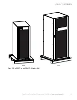
Страница 33: ...n and Unpacking Eaton 93E Integrated Transformer Cabinet ITC Installation Manual P 164000074 Rev 3 www eaton com powerquality 3 15 Figure 3 7 Eaton 93E 30ITC and Eaton 93E 60ITC as Shipped on Pallet 93E 30ITC 93E 60ITC ...

Страница 34: ...d the 93E 60ITC Figure 3 8 Eaton 93E 30ITC and Eaton 93E 60ITC Transformer Breaker Locations Front Views with Doors Removed 93E 30ITC 93E 60ITC Optional Output Transformer UPS Output Breaker Input Transformer Input Breaker Optional Output Transformer Output Breaker Input Transformer UPS Input Breaker Optional Output Transformer UPS Output Breaker Input Transformer Input Breaker Optional Output Tra...

Страница 35: ...large seams to prevent a smooth roll off of the cabinet 4 2 1 Unloading the 30ITC To remove the pallet 1 If not already completed use a forklift or pallet jack to move the ITC to the installation area or as close as possible before unloading from the pallet Insert the forklift or pallet jack forks between the supports on the bottom of the pallet see Figure 3 3 for the ITC cabinet center of gravity...

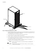
Страница 36: ... Remove two bolts securing the pallet extension plate to the pallet and remove the plate see Figure 4 1 9 Install the pallet extension plate onto the rear of the pallet using the retained bolts see Figure 4 3 Use the mounting holes provided in the pallet see Figure 4 2 10 Use a forklift or pallet jack between the supports on the bottom of the pallet to lift the pallet by approximately 3 mm 1 8 and...

Страница 37: ...rd the rear of the pallet When the pallet tilts continue rolling the cabinet down the pallet extension plate until the cabinet is clear of the pallet 12 Roll the ITC to the final installation location to the left of the UPS cabinet Verify that the doors are flush with each other 13 If installing the cabinet permanently retain the shipping brackets and hardware otherwise recycle the pallet and ship...

Страница 38: ...n Steps 4 and 5 reinstall the shipping brackets to the front and rear of the ITC with the angle facing outward see Figure 4 1 and Figure 4 2 17 Secure the cabinet to the floor with customer supplied hardware 18 If installing a second ITC for dual feed repeat Steps 1 through 17 otherwise continue to Step 19 Install the second ITC on the left side of the first ITC 19 Proceed to paragraph 4 3 NOTE Us...

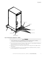
Страница 39: ...binet to become unbalanced To prevent tipping the cabinet raise and lower the jacking bolts evenly CAUTION CABINET MAY TIP Raise the EBC no more than 3 mm 1 8 above the floor just enough to allow the removal of the pallet skids 5 Turn each jacking bolt consecutively two full turns until the pallet skids clear the floor by approximately 3 mm 1 8 6 Remove the hardware loosened in Step 4 Pull the two...

Страница 40: ...o Step 19 16 Locate the two floor mounting brackets from the parts kit 17 Using the retained cabinet mounting bolts install the floor mounting brackets to the front and rear of the ITC with the angle facing outward 18 Secure the cabinet to the floor with customer supplied hardware 19 If installing a second ITC for dual feed repeat Steps 1 through 19 otherwise proceed to Step 20 Install the second ...

Страница 41: ...powerquality 4 7 Figure 4 4 Removing the Pallet Skids and Supports 93E 60ITC Front Door Jacking Bolt 2 places front 2 places rear Floor Protector 2 places front 2 places rear Rear Support Front Support Pallet Skid SkidMountingBolts 4 places front 4 places rear Cabinet Mounting Bolts 4 places front 4 places rear ...

Страница 42: ... input and output conduits 4 Using the hardware provided install the terminal cover base to the back panel of the ITC using the existing cabinet screw holes see Figure 4 6 5 Continue to paragraph 4 4 Figure 4 5 ITC Power Terminal Cover Parts NOTE Wiring can be installed using conduit between cabinets or by routing wiring through the power terminal cover base wiring channels Top Left Side Conduit L...

Страница 43: ...3E 30ITC Power Terminal Cover Base Installation and Conduit Wire Entry Location Alternate Conduit Landing Plate for Transformer Input and Output Remove panel to drill or punch conduit holes or remove knockouts Conduit Landing for Transformer Input and Output when using conduit Install conduit to bottom of base Power Terminal Cover Base Installed ...

Страница 44: ...nal safety shield panel and remove the panel to gain access to the input and output breaker terminals Retain the hardware for later use 3 Install conduit between the utility source and the ITC Alternate Conduit Landing Plate for Transformer Input and Output Remove panel to drill or punch conduit holes or remove knockouts Conduit Landing for Transformer Input and Output when using conduit Install c...

Страница 45: ...hase A B C Neutral and Ground ITC output power wiring to the ITC AC output to UPS neutral and ground terminals See paragraph 3 2 2 for wiring and termination requirements 12 Install the power terminal cover top using the provided hardware see Figure 4 17 13 Install the power terminal cover right and left sides using the provided hardware see Figure 4 17 14 Skip to Step 22 15 Route the UPS rectifie...

Страница 46: ...Installation 4 12 Eaton 93E Integrated Transformer Cabinet ITC Installation Manual P 164000074 Rev 3 www eaton com powerquality Figure 4 8 Wire Tray Location 93E 30ITC Wire Tray ...

Страница 47: ...Installation Eaton 93E Integrated Transformer Cabinet ITC Installation Manual P 164000074 Rev 3 www eaton com powerquality 4 13 Figure 4 9 Wire Tray Location 93E 60ITC Wire Tray ...

Страница 48: ...e Figure 4 11 for detail 208 Vac Input from UPS A B C See Figure 4 11 for detail 480 Vac Input to Transformer A B C See Figure 4 12 for detail 208 Vac Output to UPS A B C See Figure 4 12 for detail Optional Output Transformer Output Breaker Optional Output Transformer UPS Output Breaker Input Transformer Input Breaker Input Transformer UPS Input Breaker T2 Load Neutral Terminals T1 UPS Neutral Ter...

Страница 49: ...minal Detail 93E 30ITC Output Transformer UPS Output Breaker Phase A XOB 2 Phase B XOB 4 Phase C XOB 6 480 Vac Output to Critical Load 208 Vac Output from UPS Phase A UOB 2 Phase B UOB 4 Phase C UOB 6 Output Transformer Output Breaker Input Transformer UPS Input Breaker Phase A XIB 2 Phase B XIB 4 Phase C XIB 6 480 Vac Input to Transformer 208 Vac Input to UPS Phase A UIB 2 Phase B UIB 4 Phase C U...

Страница 50: ...e Figure 4 13 for detail 208 Vac Input from UPS A B C See Figure 4 13 for detail 480 Vac Input to Transformer A B C See Figure 4 14 for detail 208 Vac Output to UPS A B C See Figure 4 14 for detail Optional Output Transformer Output Breaker Optional Output Transformer UPS Output Breaker Input Transformer Input Breaker Input Transformer UPS Input Breaker T2 Load Neutral Terminals T2 UPS Neutral Ter...

Страница 51: ...minal Detail 93E 60ITC Output Transformer UPS Output Breaker Phase A XOB 2 Phase B XOB 4 Phase C XOB 6 480 Vac Output to Critical Load 208 Vac Output from UPS Phase A UOB 2 Phase B UOB 4 Phase C UOB 6 Output Transformer Output Breaker Input Transformer UPS Input Breaker Phase A XIB 2 Phase B XIB 4 Phase C XIB 6 480 Vac Input to Transformer 208 Vac Input to UPS Phase A UIB 2 Phase B UIB 4 Phase C U...

Страница 52: ... 30 kVA UPS UPS Power Terminal Cover Base Wiring Channel ITC Power Terminal Cover Base Wiring Channel NOTE 1 The 93E 30ITC and 93E 30 kVA UPS are shown The 93E 60ITC and 93E 60 kVA UPS installation is the same NOTE 2 The UPS and ITC are shown adjacent but other installed accessory cabinets may be adjacent in large systems with multiple cabinets However the power terminal base wiring channels are t...

Страница 53: ...inal Cover Install Power Terminal Cover Left Side Installed Power Terminal Cover Right Side Installed Power Terminal Cover Top Installed NOTE 1 The 93E 30ITC is shown The 93E 60ITC installation is the same NOTE 2 Do not install the Power Terminal Cover Left and or Right Side covers if wiring adjacent cabinets using the power terminal base wiring channel ...

Страница 54: ...t breaker terminals Retain the hardware for later use 3 Install conduit between the utility source and the ITC 93E 30ITC 93E 30 kVA UPS Power Terminal Cover Right Side Installed Power Terminal Cover Top Installed Power Terminal Cover Splice Installed Power Terminal Cover Left Side Installed Power Terminal Cover Top Installed NOTE 1 The 93E 30ITC and 93E 30 kVA UPS are shown The 93E 60ITC and 93E 6...

Страница 55: ...ct phase A B C Neutral and Ground ITC output power wiring to the ITC AC output to UPS neutral and ground terminals See paragraph 3 2 2 for wiring and termination requirements 12 Route the UPS output wiring phase A B and C and Ground from the ITC through the wire tray and the conduit to the UPS terminal block on the back of the UPS See Figure 4 10 or Figure 4 13 for ITC terminal locations See parag...

Страница 56: ...inals See paragraph 3 2 2 for wiring and termination requirements 27 If wiring to an IAC D continue to Step 28 otherwise skip to Step 30 28 Route the critical load output wiring phase A B and C Neutral and Ground from the IAC D through the power terminal cover base wiring channels see Figure 4 16 and the wire tray on the back of the ITC to the ITC AC output to critical load terminals See Figure 4 ...

Страница 57: ...nts 8 If installing wiring using conduit continue to Step 9 if using the power terminal cover base channels skip to Step 19 9 Punch or drill holes in the bottom of the power terminal cover base on the UPS cabinet for the UPS rectifier and bypass input conduits Refer to the applicable Eaton 93E UPS Installation and Operation manual listed in paragraph 1 6 for UPS cabinet conduit landing location 10...

Страница 58: ...rdware see Figure 4 18 27 Install the splice cover using the provided hardware see Figure 4 18 28 Reinstall the internal safety shield panel removed in Step 2 29 Close the outside door and secure the latch 30 After the ITC is installed and wired return to the applicable Eaton 93E UPS Installation and Operation manual listed in paragraph 1 6 to complete the UPS wiring 4 4 4 Dual Feed UPS with Two I...

Страница 59: ...e 4 13 for ITC terminal locations See paragraph 3 2 2 Table 3 4 and Table 3 5 for ITC wiring and termination requirements Refer to the applicable Eaton 93E UPS Installation and Operation manual listed in paragraph 1 6 for their respective terminal locations and termination requirements 17 Connect phase A B C and Ground UPS output power wiring from the ITC1 to the UPS output and ground terminals Se...

Страница 60: ...IAC D continue to Step 34 otherwise skip to Step 36 34 Route the critical load output wiring phase A B and C Neutral and Ground from the IAC D through the power terminal cover base wiring channels see Figure 4 16 and the wire tray on the back of the ITC1 to the ITC1 AC output to critical load terminals See Figure 4 10 or Figure 4 13 for ITC terminal locations See paragraph 3 2 2 Table 3 4 and Tabl...

Страница 61: ...service representative cannot perform any installation tasks other than verifying software and operating setup parameters Service personnel may request a copy of the completed Installation Checklist to verify all applicable equipment installations have been completed Installation Checklist o All packing materials and restraints have been removed from each cabinet o The ITC is installed on a level ...

Страница 62: ..._____________________ ________________________________________________________________________ ________________________________________________________________________ ________________________________________________________________________ ________________________________________________________________________ ________________________________________________________________________ _____________...

Страница 63: ...hematics 5 1 Onelines Figure 5 1 shows the simplified internal structure of the Integrated Transformer Cabinet ITC and Figure 5 2 a simplified UPS EBC and ITC intercabinet connection diagram Figure 5 1 93E 30ITC and 93E 60ITC Internal Oneline A C B D NOTE Callout letters A and B map to Table 3 4 Callout letters A B C and D map to Table 3 5 ...

Страница 64: ...abinet ITC Installation Manual P 164000074 Rev 3 www eaton com powerquality Figure 5 2 Dual Transformer 93E 30ITC and 93E 60ITC Intercabinet Interconnection Oneline EBC 1 EBC 2 UPS 93E ITC 93E 93E 93E AC Output to Critical Load Two Cabinets Maximum AC Input to ITC ...

Страница 65: ...Cabinet ITC Installation Manual P 164000074 Rev 3 www eaton com powerquality 5 2 Schematics Figure 5 3 shows the 93E 30ITC and 93E 60ITC schematics Figure 5 3 93E 30ITC and 93E 60ITC Schematic LEGEND Factory Wiring Customer Wiring 105 C Insulation 90 C Insulation ...

Страница 66: ...Onelines and Schematics 5 4 Eaton 93E Integrated Transformer Cabinet ITC Installation Manual P 164000074 Rev 3 www eaton com powerquality This page intentionally left blank ...

Страница 67: ...al state of any cabinet in the UPS system 6 2 Performing Preventive Maintenance The UPS system requires very little preventive maintenance However the system should be inspected periodically to verify that the units are operating normally Record maintenance results and any corrective actions in a suitable log 6 2 1 DAILY Maintenance Perform the following steps daily 1 Check the area surrounding th...

Страница 68: ...not discard waste electrical or electronic equipment WEEE in the trash For proper disposal contact your local recycling reuse or hazardous waste center 6 4 Maintenance Training A basic training course available from Eaton Corporation gives you a competent working knowledge of the UPS system operation and teaches you how to perform first level corrective maintenance For more information about train...

Страница 69: ... Output Transformer Integrated Transformer Cabinet ITC Models Description Eaton 93E 30ITC ITC for Eaton 93E 30 kVA UPS Eaton 93E 60ITC ITC for Eaton 93E 60 kVA UPS Operating Input Voltage Range 480 Vac nominal 60 Hz Input Wiring 3W G Operating Frequency Range 60 Hz 5 Hz Operating Input Current See Table 3 4 and Table 3 5 Operating Output Voltage Range 208Y 120 Vac nominal 60 Hz Output Wiring 4W G ...

Страница 70: ...perature 13 F to 140 F 25 C to 60 C Storage Temperature 13 F to 131 F 25 C to 55 C Operating Altitude Maximum 1500m 5000 ft at 30 C without derating Transit Altitude 15000m 49213 ft Ventilation 30ITC forced air cooling 60ITC convection Relative Humidity operating and storage 5 to 95 maximum noncondensing Acoustical Noise Not applicable Safety Conformance UL1778 4th edition Agency Markings ULus EMC...

Страница 71: ...aton shall become the property of Eaton LIMITED WARRANTY PERIOD The period covered by this Warranty for Product installed and currently located in the fifty 50 United States and the District of Columbia is six 6 months from the date of Product purchase for labor coverage when no startup is performed by an authorized Eaton Customer Service Engineer or Agent or twelve 12 months from the date of Prod...

Страница 72: ...e the benefits of this Warranty the End User must register the product warranty via mail or online at www powerquality eaton com Product Registration product registration use the Product in a normal way follow the Product s user s guide and protect against further damage to the Product if there is a covered defect OTHER LIMITATIONS Eaton s obligations under this Warranty are expressly conditioned ...

Страница 73: ......

Страница 74: ... P 164000074 3 P 164000074 3 ...

Отзывы: