background image

C-model 8-20 kW

frame

15/20 kW

frame

30/40 kW

frame

Note: Maximum number of internal batteries are included with all the models (except the

C-model, which has no internal batteries).

The UPS cabinets use forced air cooling to regulate internal component

temperature. By default, air inlets are in the front of the cabinet and outlets are

in the back. Allow clearance in front of and behind each cabinet for proper air

circulation.
The clearance required around the UPS cabinet is shown in Table 

.

Note: This equipment is not intended for building-in, rack-mounting or for

incorporation in larger equipment.

Table 9: UPS cabinet minimum clearances

15/20 kW frame*

30/40 kW frame

From the top of the cabinet

500 mm

500 mm

From the front of the cabinet

650 mm

650 mm

From the back of the cabinet

150 mm

250 mm

From the side of the cabinet

0 mm

0 mm

* Applies to the 20 kW C-model frame as well.

Eaton 91PS/93PS UPS 8–40 kW

User's and installation guide

©

 Eaton Corporation plc 2018. All rights reserved.

Revision: 005

Document ID: P-164000493

36 (117)

Содержание 91PS UPS 8-40 kW

Страница 1: ...User s and installation guide Eaton 91PS 93PS UPS 8 40 kW P 164000493...

Страница 2: ...e information contained in this manual but no liability can be accepted for any errors or omission The right to make design modifications is reserved Unauthorized copying and lending are prohibited Ea...

Страница 3: ...3 2 2 Stored energy and battery mode 23 3 2 3 Bypass mode 25 3 3 UPS features 27 3 3 1 Advanced Battery Management 27 3 3 2 Powerware Hot Sync 27 3 3 3 Power Conditioner 28 3 3 4 Frequency Converter 2...

Страница 4: ...e connections in a parallel system 63 5 6 Wiring parallel 91PS 93PS UPS systems 64 5 6 1 Power wiring overview 64 5 6 2 Control signals overview 66 5 6 3 Installing parallel control wiring 67 5 7 UPS...

Страница 5: ...4 3 Enabling and disabling the battery charger 94 7 5 UPM control instructions 95 7 5 1 Starting the UPMs 95 7 5 2 Shutting down the UPMs 95 7 6 Using the Remote Emergency Power off switch 96 7 7 Turn...

Страница 6: ...l 110 10 2 Whom to contact in case of Warranty 111 11 Appendix A Recommended secure hardening guidelines 112 Eaton 91PS 93PS UPS 8 40 kW User s and installation guide Eaton Corporation plc 2018 All ri...

Страница 7: ...could result in minor or moderate injury or damage to your machine Note Notes are used to indicate important information and useful tips 1 2 Safety symbols 1 2 1 Hazard symbols These symbols indicate...

Страница 8: ...n procedures and menu options or represents a command or option that you type or enter at a prompt Italic type highlights notes and new terms when they are defined Screen type represents information t...

Страница 9: ...aintenance Isolation Switch MOB Module Output Breaker REPO Remote Emergency Power off RIS Rectifier Input Switch SCR Silicon controlled Rectifier SNMP Simple Network Management Protocol STSW Static by...

Страница 10: ...nnel can install and service it DANGER This UPS carries lethal voltages All repairs and service must be done by authorized personnel only There are no user serviceable parts inside the UPS WARNING The...

Страница 11: ...e batteries when the UPS is in the Battery mode Make sure that your replacement batteries are of the same number and type as the battery that was originally installed in the UPS See more accurate inst...

Страница 12: ...r perform work on the UPS 2 2 CE marking The product has a CE marking in compliance with the following European directives LVD Directive Safety 2014 35 EU EMC Directive 2014 30 EU RoHS Directive 2011...

Страница 13: ...t exceeding the specifications Excessive amount of dust in the operating environment of the UPS may cause damage or lead to malfunction Always protect the UPS from the outside weather and sunshine In...

Страница 14: ...waste center 2 6 For more information Address any inquiries about the UPS and the battery cabinet to the local office or an agent authorized by the manufacturer Quote the type code and the serial numb...

Страница 15: ...peration During brownouts blackouts and other power interruptions batteries provide emergency power to safeguard operation The UPS system is housed in a single free standing cabinet with safety shield...

Страница 16: ...odules Note Startup and operational checks must be done by an authorized Eaton Customer Service Engineer or by other qualified service personnel authorized by Eaton or the terms specified in the Warra...

Страница 17: ...ernal batteries 5 Communications area The system level static bypass in the UPS cabinet determines the attainable output power of the UPS The static bypass line consists of a static switch and a backf...

Страница 18: ...paralleled internally The rectifier input switch and battery breaker are available as standard for all the models The internal MBS is available as option for all the models If utility power is interru...

Страница 19: ...transfer to on line mode with less than 2 ms transition time Energy Saver System ESS mode Critical load is supported securely by utility power through the static bypass switch with double conversion...

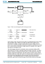
Страница 20: ...put Main power flow B Rectifier 2 Rectifier in put Energized C Inverter 3 Output De energized D Battery con verter 4 Battery breaker Trickle current E Battery Closed Open Three phase AC input power is...

Страница 21: ...in operation In an external parallel redundant system each UPS can be isolated from the system for service while the remaining UPSs support the load in the double conversion mode 3 2 1 2 Variable Mod...

Страница 22: ...gized D Battery con verter 4 Battery breaker Trickle current E Battery Closed Open In the ESS mode the UPS safely provides mains current directly to the load when the input is within the acceptable li...

Страница 23: ...ng sure that clean power is delivered to the facility The energy saver system increases system efficiency when supplying 20 100 of nominal load reducing energy losses by up to 80 3 2 2 Stored energy a...

Страница 24: ...lied from the same source as the UPS rectifier the backfeed protection contactor K5 also opens The opening of K1 and K5 prevent system voltages from bleeding backwards and re entering the input source...

Страница 25: ...The bypass source supplies the commercial AC power to the load directly The UPS can also be commanded to transfer to the bypass mode manually through the display The UPS status indicated on the displa...

Страница 26: ...ailable to the output of the system in the bypass mode The static bypass consists of a solid state silicon controlled rectifier SCR static switch STSW and a backfeed protection isolation device K5 The...

Страница 27: ...ging is resumed when necessary 3 3 2 Powerware Hot Sync The Eaton Powerware Hot Sync technology is an algorithm that eliminates the single point of failure in a parallel system and therefore enhances...

Страница 28: ...vailable 3 3 4 Frequency Converter The Frequency Converter mode is characterized by the UPS running without the bypass mode available The output frequency can be configured to be different from the st...

Страница 29: ...et The EMBS contains a rotary switch MBP MIS to change the source that supplies the load between the UPS output and the mechanical bypass It may additionally include two switches one for the rectifier...

Страница 30: ...urations UPS power rating The maximum attainable UPS system power rating is determined by the size of the UPS cabinet frame The number of UPM power modules determines the nominal power rating of the U...

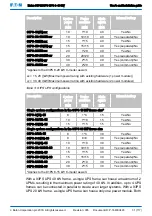
Страница 31: ...91PS 8 15 15 8 1 8 15 Yes No 91PS 10 15 15 10 1 10 15 Yes No 91PS 15 15 15 15 1 15 15 Yes No Single system configurations in the 91PS 30 kW frame size 91PS 8 30 15 8 1 8 30 Yes No 91PS 8 8 30 30 8 8...

Страница 32: ...system control and monitoring Standard SNMP web interface Standard Internal MBS Optional Rectifier input switch S1 Standard Internal battery breaker CB1 Standard Battery start Standard Integrated back...

Страница 33: ...ngineer or by other qualified service personnel authorized by Eaton or the terms specified in the Warranty see Chapter 10 become void This service is offered as a part of the sales contract for the UP...

Страница 34: ...ted within 7 5 meters of the UPS equip ment The Remote Emergency Power off REPO device is mounted in its in stalled location and its wiring is terminated inside the UPS cabinet If EPO is used in the N...

Страница 35: ...ION Do not stack anything on top of the UPS cabinet Do not stack the UPS 91PS 93PS C model cabinet on top of any other similar cabinet s If installed on a shelf use suitable supports to prevent the UP...

Страница 36: ...rculation The clearance required around the UPS cabinet is shown in Table 9 Note This equipment is not intended for building in rack mounting or for incorporation in larger equipment Table 9 UPS cabin...

Страница 37: ...imum requires the airflow of 600 m3 per 1 kW of losses Temperature rise of 10 C maximum requires the airflow of 300 m3 per 1 kW of losses An ambient temperature from 20 C to 25 C is recommended to ach...

Страница 38: ...tilation must be provided to locations where the UPS and batteries are located For the 15 20kW frame with internal batteries the minimum air flow is 3 m3 hour and the minimum free area of opening for...

Страница 39: ...breaker If a bypass input breaker is installed in the maintenance bypass and a single feed UPS is being installed a single feed to the maintenance bypass is acceptable for supplying both the UPS and...

Страница 40: ...nput terminal with a wire suitable for the bypass rating of the unit A readily accessible disconnect device must be incorporated in all fixed input wiring WARNING Do not disconnect the bypass neutral...

Страница 41: ...20 30 40 Pos neg line mm2 1 16 1 16 1 16 1 16 1 35 1 35 Battery fuse A 63 63 63 63 160 160 PE cable mm2 1 16 1 16 1 16 1 16 1 16 1 16 Maximum conductor cross section 20 kW frame 20 kW C model and 40 k...

Страница 42: ...24 V shunt release with early make auxiliary contact together with the above circuit breakers Type Article No NZM1 XAHIVL24AC DC 259792 P 152001062 Note In 93PS UPS C model the internal and external...

Страница 43: ...Maximum output bypass current calculated at continuous 125 overload and at 15 voltage tolerance 3 Maximum battery current calculated at rated load and 1 67 V cell voltage for the default 32 block stri...

Страница 44: ...25 83 Notes 1 Maximum rectifier current calculated at the minimum voltage tolerance Figure 10 Power cable terminals in the 91PS 15 kW frame X1 Rectifier input X4 External battery X2 Bypass input TB20...

Страница 45: ...Bypass input TB20 External battery trip and aux sig nal N O X3 UPS output PE Protective earth X4 External battery A Connection information sticker Eaton 91PS 93PS UPS 8 40 kW User s and installation...

Страница 46: ...input X4 External battery X2 Bypass input TB20 External battery trip and aux sig nal N O X3 UPS output PE Protective earth X4 External battery Eaton 91PS 93PS UPS 8 40 kW User s and installation guide...

Страница 47: ...battery for UPM2 X3 UPS output TB20 External battery trip and aux sig nal N O for UPM1 X4 1 External battery for UPM1 TB21 External battery trip and aux sig nal N O X4 3 External battery for UPM2 PE...

Страница 48: ...input X4 External battery X2 Bypass input TB20 External battery trip and aux sig nal N O X3 UPS output PE Protective earth X4 External battery Eaton 91PS 93PS UPS 8 40 kW User s and installation guide...

Страница 49: ...earth Note External overcurrent protection is not provided by this product but is required by codes Refer to Table 12 for wiring requirements If a lockable output disconnect is required it must be su...

Страница 50: ...d unbalance is 50 or less Source protection for the AC input to bypass must suit the characteristics of the load and take into account effects such as inrush or starting current Bypass input and outpu...

Страница 51: ...orklift or other material handling equipment to move the cabinet to the installation area Insert the forks of the forklift between the skids on the bottom of the unit 2 Make a visual inspection and ex...

Страница 52: ...ch it to the pallet with nails or screws so that it can be safely used for wheeling the UPS off the pallet 5 If the leveling feet are not fully retracted turn them until they are retracted Eaton 91PS...

Страница 53: ...he shipping brackets move the unit immediately away from the pallet After you have removed the shipping brackets and retracted the leveling feet do not use a forklift to move the unit while it is stil...

Страница 54: ...the cabinet is level With the 15 20 kw frame reattach the shipping brackets to the UPS cabinet to provide extra support There are 2 options for positioning the shipping brackets on both sides of the...

Страница 55: ...ton CAUTION To avoid physical injury or death or damage to the UPS or the load equipment follow these instructions during the UPS system installation CAUTION In case of condensed moisture inside the U...

Страница 56: ...ector locations in the 30 40 kW frame 1 Connectors 2 Gland plate 1 To gain access to the terminal blocks remove the screws securing the gland plate at the back of the UPS Eaton 91PS 93PS UPS 8 40 kW U...

Страница 57: ...o the respective terminals and peripherals For detailed information see Figures 26 and 27 and Sections 5 4 and 5 5 7 Assemble the internal batteries into the battery trays Connect the battery blocks i...

Страница 58: ...es and regulations Only qualified personnel may install the battery system Battery cables must be protected against current and thermal overload that is the battery system must include proper fuses or...

Страница 59: ...ery power cabling For the 91PS 93PS there are two different battery cabinets EBC A and EBC B The UPSs use 32 battery blocks per string CAUTION If you connect the C model 91PS 93PS UPS to an external b...

Страница 60: ...nd 11 for the recommended cable and fuse sizes 5 4 Installing a remote EPO switch A remote EPO switch can be used in case of an emergency to shut down the UPS and remove power to the critical load fro...

Страница 61: ...not for utility use For higher signaling circuit voltage requirements please use an industrial relay adapter in the MiniSlot 5 5 1 Installing customer input signals interface These inputs are located...

Страница 62: ...be activated by various events Configuration can be done by an authorized Eaton Customer Service Engineer or by other qualified service personnel authorized by Eaton 5 5 4 Industrial Relay Card interf...

Страница 63: ...and install the LAN and other cables to the appropriate MiniSlot cards The cable route is through the signal cable canal in the top section of the UPS 7 For operator instructions refer to the manual s...

Страница 64: ...parallel and tied to the bypass status relay in each UPS is used for a secondary communication path This arrangement ensures bypass control even if the CAN bus is lost WARNING Do not connect units equ...

Страница 65: ...he breaker should also disconnect the neutral for improved safety during maintenance The MOB must have a Form C auxiliary contact The N C contact is connected to the corresponding UPS s input used for...

Страница 66: ...he following must be true 1A 1B 2A 2B 3A 3B 4A 4B Any differences in wire length result in decreased capacity and improper operation of the UPS system while in the bypass mode 5 6 2 Control signals ov...

Страница 67: ...ity device These inputs can be configured with action items The following action items affect all the UPSs in the system When an action item is active on a UPS and the MOB is closed the action item is...

Страница 68: ...installed D UPS 4 if installed Note This drawing is for distributed bypass wiring purposes and it is not a floor layout plan UPSs can be placed in any physical order Eaton 91PS 93PS UPS 8 40 kW User...

Страница 69: ...B7 2 CAN GND Connect the shield on one end only Note NC and NO designations on MOB AUX contacts are defined with the breaker in the OFF open position If the MOB contacts have pigtail leads use the sam...

Страница 70: ...an be programmed to display the alarm s functional name LAN drops for use with MiniSlot cards are provided by facility planners or the operator The UPS Battery Aux and 24 VDC Shunt Trip signal wiring...

Страница 71: ...s characteristic The UPS has the following communication interfaces 1 MiniSlot 1 2 MiniSlot 2 3 USB device connection to computer 4 Communication cable conduit 5 Emergency Power Off EPO 6 Relay output...

Страница 72: ...mination 12 TB3 not used 5 TB7 external CAN 13 Serial COM port RS 232 6 TB6 pull chain bus 14 MiniSlot 2 7 USB1 USB host connection to accessories 15 TB4 EPO 8 USB2 USB device connection to computer 1...

Страница 73: ...nal input 3 return Pin 6 Signal input 3 Pin 7 Signal input 2 return Pin 8 Signal input 2 Pin 9 Signal input 1 return Pin 10 Signal input 1 TB4 EPO Pin 1 EPO normal closed Pin 2 EPO normal closed retur...

Страница 74: ...t 10 100BaseT network Figure 28 Network Card MS PX Gateway Card Provides remote monitoring through a Web browser interface e mail and a network management system NMS using SNMP and connects to a twist...

Страница 75: ...ions by allowing up to 250 volts and 8 Amperes through its 5 relay connections By connecting wires to the corresponding places in its terminal blocks you can choose Normally Open or Normally Closed se...

Страница 76: ...n disaster recovery and load shedding features in virtualized environments Intelligent Power Protector IPP is a shutdown agent with basic monitoring and alarming capability It provides automatic grace...

Страница 77: ...Additionally each of the 2 MiniSlots can be equipped with a relay card including 5 relays The instructions guide you through the relay configuration Currently the relay configuration can be done only...

Страница 78: ...puts in the Configurations screen 6 Select out of the following options Native Alarm relay It is possible to set 8 different events for the native relay If any of the set events occurs the relay is ac...

Страница 79: ...y 9 If you selected one of the MiniSlots the following default values are available Relay 1 262 On Line LED is lit Relay 2 260 On Battery LED is lit Relay 3 416 Alarm LED is lit Relay 4 261 On Bypass...

Страница 80: ...it opening for up to 12 mm conduit 3 K1 thru K5 terminal connections for relay contacts to operator s monitoring equipment 2 Signal input connector with voltage supply Eaton 91PS 93PS UPS 8 40 kW User...

Страница 81: ...l voltages 220 380 230 400 or 240 415 VAC Before you start to operate the UPS confirm the UPS nominal voltage and frequency from the display by selecting Settings Information If the UPS need to be ope...

Страница 82: ...status indicators They are colored light emitting diode LED lamps and they work in conjunction with the alarm horn to let you know the operating status of the UPS Table 20 Status indicators Indicator...

Страница 83: ...of two rows of LEDs located on the left and right sides of the UPS cabinet door The LEDs are red green and yellow RGY The color of the LED is used to indicate the condition of the UPS The most urgent...

Страница 84: ...double conversion mode Only the green indicator for normal operation is visible during normal UPS system operation The other indicators illuminate to indicate alarms or events When an alarm occurs fi...

Страница 85: ...ss meters Detailed information on UPS or system bypass me ters Output meters Detailed information on UPS or system output me ters UPM Power Battery meters Detailed information on UPS or system battery...

Страница 86: ...module Start module UPM 1 Charger Battery test UPM status UPM 2 Charger Battery test UPM status EAA controls ESS Enable Disable Configure VMMS Enable Disable Configure Enable High Alert Clear status...

Страница 87: ...details Details are available by pressing on different statis tics Settings User Configura tion Service Configurable user settings For details see Section 7 1 4 1 7 1 4 1 User settings The UPS includ...

Страница 88: ...Press the lock icon in the top right corner of the screen 2 Type in your password and press OK You are signed in 3 Press Continue to return to the previous screen You have 3 attempts to type in the p...

Страница 89: ...een STARTING ONLINE The UPS system is now operating in the double conversion mode The green status indicator for normal operation is illuminated in all the UPSs in the system 7 3 2 Starting the UPS sy...

Страница 90: ...the power processor remains on and an alarm sounds The UPS system is now operating in the bypass mode and the yellow bypass status indicator is illuminated The UPM status is shown as Ready The system...

Страница 91: ...m mode commands are displayed only if enabled at the factory or by an authorized Eaton Customer Service Engineer To transfer the critical load to the double conversion mode 1 In the home screen press...

Страница 92: ...ery mode and then to the double conversion mode If the power module is not available the system remains in the bypass mode and an alarm sounds The green status indicator for normal operation is illumi...

Страница 93: ...cted Only use this feature when you want to de energize the critical load When Load Off is selected the input output and bypass backfeed contactors open the battery breaker CB1 or disconnect is trippe...

Страница 94: ...tially on the UPS status line STARTING ONLINE The UPS system is now operating in the double conversion mode and the green status indicator for normal operation is illuminated 7 4 2 Shutting down a sin...

Страница 95: ...ule controls The Select module screen is displayed 12 Select the UPM you want to start The UPM control screen is displayed The UPM status is shown as SHUTDOWN 13 In the UPM control screen select Start...

Страница 96: ...mentation provided with the switch To use the EPO switch 1 Press the EPO pushbutton switch The input output and bypass backfeed relays open the battery breaker or disconnect is tripped and the power m...

Страница 97: ...put C Out 2 Perform the transfer from the double conversion mode to the bypass mode as instructed in Section 7 3 3 Remember to verify the transfer before proceeding to the next step 3 Turn the MBS fro...

Страница 98: ...e UPS back to the double conversion mode 1 Follow the normal start position Figure 40 Maintenance bypass mode A Static bypass input 1 Maintenance Bypass Switch MBS B Rectifier input C Out 2 Turn on th...

Страница 99: ...on to the UPS position 7 Perform the transfer from the bypass mode to the double conversion mode as described in Section 7 3 4 The UPS is now in the double conversion mode Figure 41 Double conversion...

Страница 100: ...isconnecting the utility power and the DC power authorized service personnel must wait at least 5 minutes for capacitor bleed off before attempting internal access to the UPS module DANGER LETHAL VOLT...

Страница 101: ...source of the ground Contact with any part of a grounded battery can result in an electrical shock The likelihood of such a shock is reduced if such grounds are removed during installation and mainte...

Страница 102: ...m if needed Contact your service representative for replacement filters To replace the filters a Open the UPS front door b Replace the filters c Close the UPS front door 3 Record the check results and...

Страница 103: ...to the risk caused by high energy and voltage Do not discard waste electrical or electronic equipment in the trash For proper disposal contact your local collecting recycling reuse or hazardous waste...

Страница 104: ...and flammable substances If used improperly batteries can injure or kill people and damage equipment Do not discard of unwanted batteries or battery material in the public waste disposal system Follow...

Страница 105: ...e information about training and other services contact your Eaton representative Eaton 91PS 93PS UPS 8 40 kW User s and installation guide Eaton Corporation plc 2018 All rights reserved Revision 005...

Страница 106: ...UPS Part 4 Environmental Aspects Requirements and Reporting IEC 62430 Environmentally conscious design for electrical and electronic products RoHS 2011 65 EU on the restriction of the use of certain h...

Страница 107: ...ases or 1 phase N Rated output voltage 220 380 V 230 400 V 240 415 V configu rable Rated output frequency 50 or 60 Hz user configurable Total voltage harmonic distortion 100 linear load 1 5 100 non li...

Страница 108: ...000 m 3 300 ft above sea level at 40 C Maximum 2 000 m 6 600 ft with 1 de rating per each additional 100 m above 1 000 m Maximum storage time with internal batter ies 6 months without recharge Maximu...

Страница 109: ...e 0 25 A 1 25 A with the 20 kW UPM at 80 load limited to 15 A 1 18 A with the 15 kW UPM at 80 load limited to 10 A 8 40 kW units two UPMs Configurable 0 50 A at 80 load auto matically limited to 30 A...

Страница 110: ...lified service personnel authorized by Eaton Otherwise the warranty will be voided If the product fails to meet its published specifications due to a defect in material and workmanship covered by this...

Страница 111: ...ere the unit was purchased Have the following information available Purchase order number and purchase order date Installation date OR Serial number and part number of the unit information available o...

Страница 112: ...lso offers Cybersecurity Best Practices whitepapers to its customers that can be referenced at www eaton com cybersecurity Table 24 Secure configuration guidelines Category Description Asset identific...

Страница 113: ...net to another cabinet An attacker with unauthorized physical access to the device could cause serious disruption of the device functionality A combination of physical access con trols to the location...

Страница 114: ...t administrative privileges Threat actors are increasingly focused on gaining control of legitimate credentials especially those associated with highly privileged accounts Limit privileges to only tho...

Страница 115: ...r upgrade Our company also has a robust vulnerability response process In the event of any security vulnerability getting discovered in its products our company patches the vul nerability and releases...

Страница 116: ..._EAS WP910003EN pdf 3 NIST SP 800 82 Rev 2 Guide to Industrial Control Systems ICS Security May 2015 https ics cert us cert gov Standards and References 4 National Institute of Technology NIST Interag...

Страница 117: ...Copyright 2018 Eaton Corporation plc All rights reserved Unauthorized copying and lending are prohibited Eaton Power Quality Oy Koskelontie 13 FI 02920 Espoo Finland www eaton eu...

Отзывы: