background image

9

Model 72400

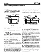
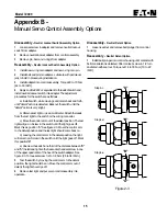
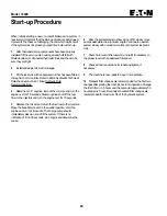
centering the servo piston assembly is required. Measure in
from the left side and set servo piston 12,7 mm [.5 in.] from
surface of housing servo bore as shown in figure 1-5.

Note: Re-adjustment may be required for neutral at unit start-up.

;

12,7 mm

[.5 in.]

Adjust to center piston

Install servo piston 
in this direction.

Figure 1-5

5

Install new seal washer, washer, and jam nut to servo

piston bolt. Holding servo piston bolt with hex key wrench
Torque jam nut 17 to 18 N•m [ 150 to 160 lbf•in]. Check the
centering of servo piston assembly. Install new cover plate
gasket and cover plate to left side of servo piston and retain with
four each washers and #10-24 cap screws. Torque cap screws
4,5 to 5,4 N•m [40 to 48 lbf•in.].

6

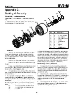
To assemble cradle sub-assembly, install bushing onto

cradle retaining with button head cap screws. Torque button
head cap screw 1,6 to 1,8 N•m [14 to 16 lbf•in.]

7

Place cradle sub-assembly into housing making sure cradle

is completely seated into housing. Retain cradle sub-assembly
with two cap screws. Torque cap screws 27 to 33 N•m [20 to 24
lbf•ft].

8

To install shaft, place exterior retaining ring, thrust race,

thrust bearing, second thrust race, and second retaining ring
onto shaft. Position washer and shaft seal or spacer onto shaft.

9

Install shaft assembly into front of housing for units with

spacer, retain with interior retaining ring and go on to step 10.
For units with shaft seal, seat seal into position with seal driver
and retain with interior retaining ring.

10 Install servo piston follower onto swashplate dowel pin.
Install swashplate carefully onto bushing (coat bushing surface
with hydraulic oil), aligning servo piston follower with slot in
servo piston assembly.

Disassembly and Reassembly

Housing Inspection:

 Check the bearing (press fit) in housing. If needles

remain in cage, move freely, and setting at the dimension
shown in figure 1-4, removal not required.


1,78 mm

[.07 in.]

Numbered End

Flange End of Housing

Figure 1-4

16 To remove cradle sub-assembly, remove the two cap
screws retaining cradle inside housing. Removing cradle sub-
assembly from housing.

17 Remove button head cap screws (qty. 2) to remove
bushing from cradle.

Bushing Inspection:

• Inspect bushing for contamination embedment within

coating of bushing surface coming in contact with swashplate.

18 Remove all plugs from housing.

19  Discard the shaft seal, gaskets, and  o-rings from all
assemblies. Replace with new seals upon reassembly.

Reassembly - 

Servo Controlled Piston Pump

1

All parts should be cleaned and critical moving parts

lubricated before reassembly.

2

If necessary, press new bearing in housing to dimension

shown in figure 1-4 with the numbered end of bearing outward.

3

Install the two new seal sub-assemblies into the servo

piston cavity of housing.

4

 Screw the cover plate onto the servo piston assembly.

Install new cover plate gasket in place on housing. Install servo
piston assembly and cover plate into servo piston bore in right
side of housing (as shown in figure 1-1 and figure 1-5). Retain
cover plate with four each washers and cap screws. Torque cap
screws 4.5 to 5.4 N•m [40 to 48 lbf•in.]. To obtain neutral,

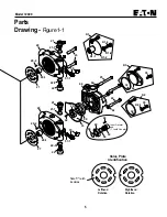
Front Flange - Drive Shaft End of Pump

Right Side

Left Side

Содержание 72400

Страница 1: ...Eaton Medium Duty Piston Pump Model 72400 Servo Controlled Piston Pump v 04 Repair Information...

Страница 2: ...p from the vehicle Cleanliness is extremely important Clean the port areas thoroughly before disconnecting the hydraulic lines Plug the pump ports and cover the open hydraulic lines immediately after...

Страница 3: ...JB Revision level of parts list Last two digits of year built 93 for 1993 etc Required Tools 9 16 in Hex Key Allen 5 32 in Hex Key Allen 5 16 in Hex Key Allen 3 32 in Hex Key Allen 5 64 in Hex Key All...

Страница 4: ...3 43 37 4 19 20 19 4 4 19 20 19 4 45 3 31 28 1 28 2 40 40 1 41 41 1 39 1 38 38 1 9 12 17 61 7 6 60 12 61 7 11 16 53 52 48 26 47 36 34 18 10 8 14 2 Serial Code and Product Number Location 51 Shaft ass...

Страница 5: ...thand Rotation Righthand Rotation 27 29 29 1 22 22 1 21 21 1 57 57 1 23 29 2 33 42 49 50 46 24 25 27 29 29 1 22 22 1 21 21 1 57 57 1 K1 K1 1 K1 4 K1 3 K1 2 K3 44 35 K2 35 K2 1 32 32 29 2 62 62 42 49 5...

Страница 6: ...D 23 4 Cap Screw 3 8 16 57 2 mm 2 25 in Long 24 2 Cap Screw 3 8 16 88 9 mm 3 5 in Long 25 2 Cap Screw 3 8 16 101 6 mm 4 0 in Long 26 6 Cap Screw 27 1 Valve Plate 28 1 Housing Assembly 28 1 1 Housing 2...

Страница 7: ...e 53 1 Control Valve Orifice 55 1 Coupler 11 tooth 56 2 Retaining Ring 57 1 Bypass Valve Actuator or Plug 57 1 1 O ring 2 21 mm Dia x 16 36 mm I D 087 in Dia x 644 in I D 60 1 Washer 61 8 Washer 62 4...

Страница 8: ...15 Remove retaining ring from the front of housing Press the shaft shaft seal or spacer and washer from housing Remove retaining ring thrust washer thrust bearing second thrust washer and second reta...

Страница 9: ...ing 10 Install servo piston follower onto swashplate dowel pin Install swashplate carefully onto bushing coat bushing surface with hydraulic oil aligning servo piston follower with slot in servo pisto...

Страница 10: ...o the endcover with steel side against endcover 17 Install endcover assembly onto housing assembly Make sure ports are positioned correctly valve plate and gasket stay in place No gerotor charge pump...

Страница 11: ...p adapter assembly It should not be scored excessively Numbered End Gerotor Pocket 2 41 mm 095 in Flange Figure 1 2 Reassembly Charge Pump Adapter Assembly 1 If necessary press new bearing or bushing...

Страница 12: ...haft Adjust set screw until it bottoms out on input shaft and back out one quarter turn 6 Install wiper seal on input shaft as shown in figure 2 2 7 Install new o ring onto plug retaining valve spool...

Страница 13: ...ches Figure 2 1 Figure 2 2 Item Qty Description 48 1 1 Control Housing 48 2 1 Plug 48 3 1 O ring 48 4 1 Retaining Ring 48 5 2 Spring Retainer 48 6 1 Spool Centering Spring 48 7 1 Valve Spool 48 8 1 Se...

Страница 14: ...ve into manifold by hand until top o ring is met by manifold Then wrench tighten to 34 N m 25 lbf ft max Loosen Nut retaining coil to reposition if necessary and re torque 5 4 to 7 N m 4 to 5 lbf ft 3...

Страница 15: ...install neutral lockout switch into adapter The adjustment procedures for the switch are as follows a Install switch while moving control arm back and forth until detent action is detected Back out t...

Страница 16: ...screw and 1 ea 3 8 in N C nut To remove spring place one of the flat washers over the 3 8 in x 3 1 4 in cap screw Put cap screw through the center of the cylinder barrel and apply the second washer Le...

Страница 17: ...Pump Suction Port Tee in line to check Inlet Vacuum Figure 3 1 Explanatory Diagram Fault Logic Trouble Shooting This fault logic trouble shooting guide is a diagnostic aid in locating transmission pr...

Страница 18: ...Ok Ok Ok 5 6 7 Symptom System Operating Hot Check Oil Level in Reservoir Fill to Proper Level Defective Below Level Repair or Replace Check System Pressure Reduce System Load High Ok 10 Inspect Charg...

Страница 19: ...pect Bypass Valve If used Repair or Replace Defective Ok Ok Ok 11 2 8 Symptom System Response Sluggish Check Charge Pressure Low Defective Repair or Replace Inspect Motor Ok 13 Inspect Servo Piston 4...

Страница 20: ...l to Proper Level Defective Below Level Repair or Replace Check System Pressure Ok 11 Inspect Charge Relief Valve Repair or Replace Defective Ok 12 Inspect Charge Pump Repair or Replace Defective 14 I...

Страница 21: ...tial or full open position 9 Inspect Inlet Screen or Filter for a plugged or clogged screen or filter element b obstructed inlet or outlet c open inlet to charge pump 10 Check System Pressure a See fi...

Страница 22: ...s and turn the engine over for 15 seconds 5 Replace the coil wire or return the fuel flow to the injectors Place the transmission unit in the neutral position start the engine and run it at a low idle...

Страница 23: ...23 Model 72400 Notes...

Страница 24: ...Order parts from number 06 06 642 Parts Information booklet Each order must include the following information 1 Product and or Part Number 2 Serial Code Number 3 Part Name 4 Quantity...

Страница 25: ...rie MN 55344 USA Tel 952 937 9800 Fax 952 294 7722 www eaton com hydraulics Eaton Fluid Power Group Hydraulics Business Europe Route de la Longeraie 7 1110 Morges Switzerland Tel 41 0 21 811 4600 Fax...

Отзывы: