


15
Model 72400
Disassembly -
Neutral Detent Option
1
Loosen seal nut and remove ball plunger from control
housing.
Reassembly -
Neutral Detent Option
1
Install ball plunger into control housing until contact with
bell crank detent is detected. After contact, screw in 1/2 turn
and retain with seal nut. Torque nut 14 to 30 N•m [10 to 22
lbf•ft].
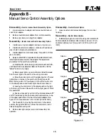
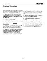
"A"
"B"
"B"
"A"
Figure 2-3
Step 4-c
Step 4-d
Step 4-e
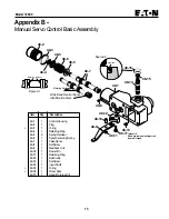
Appendix B -
Manual Servo Control Assembly Options
Disassembly -
Neutral Lockout Switch Assembly Option
1
Loosen set screw in adapter and remove neutral lockout
switch from adapter.
2
Remove neutral lockout adapter from control assembly.
3
Remove pin, ball, and o-rings from adapter.
Reassembly -
Neutral Lockout Switch Assembly Option
1
Install new o-ring onto adapter and new o-ring onto pin.
2
Install ball and pin into adapter. Lubricate with petroleum
jelly to hold in place during installation.
3
Install adapter into control assembly. Torque 60 to 70 N•m
[44 to 53 lbf•ft].
4
Apply Loctite #222 or equivalent to threads of switch and
install neutral lockout switch into adapter. The adjustment
procedures for the switch are as follows.
a) Install switch, while moving control arm back and forth,
until "detent" action is detected. Back out the switch until the
"detent" action is very slight.
b) Obtain a test light or use a multimeter. Attach the leads
from the test light to the switch or the wiring connector.
c) Move the control arm out of the detent position. The test
light will go on. Screw in the switch until the light goes off.
Mark this as position "A". See figure 2-3. Move the control arm
to the detent position and the test light should come back on.
d) Leaving the control arm in the detent position, the light
will remain on. Screw in the switch until the light goes off. Mark
this position"B".
e) Unscrew the switch one third of the distance between "B"
and "A". Install and tighten the hex socket head set screw in one
of the upper quadrants of the hex of the switch adapter. See
figure 2-3. Torque set screw 3.2 to 3.8 N•m [28 to 34 lbf•in.]
5
Test the switch by moving the control arm to the detent
position, the light should be on. Move the control arm out of
detent, the light should go off.
6
Remove test light and put servo control assembly into
operation.


