


16
Model 72400
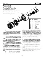
Appendix C -
Rotating Kit Assembly
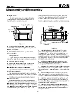
Disassembly -
Rotating Kit Assembly
Disassembly of rotating assembly is required for inspection
only.
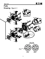
1
Remove the nine piston assemblies, shoe retainer, and
shoe retainer pivot from cylinder barrel.
Inspection:
• Examine the O.D. of the pistons for finish condition.
They should not show wear or deep scratches. Inspect the
shoes for a snug fit on the ball end of the pistons and a flat
smooth surface that comes in contact with the swashplate. Do
not lap piston shoes.
• Examine the shoe retainer for wear in the pivot area.
• Examine the pivot to insure smoothness and no signs
of wear.
• Inspect the cylinder barrel surface that makes contact
with valve plate. This surface should be smooth and free of
deep scratches. Do not lap piston block.
• The pistons should move freely in the cylinder barrel
bore. If they are sticky in the bore, examine the bore for scoring
or contamination.
2
To inspect pins and spring caution should be taken in
removing spring. The spring is highly compressed and the
retaining ring should not be removed without compressing the
spring safely.
The following parts are required to disassemble the cylinder
barrel:
2 ea.
3/8 in. I.D. x 1-1/8 in. O.D. flat washers
1 ea.
3/8 in. x 3-1/4 in. N.C. cap screw, and
1 ea.
3/8 in. N.C. nut
To remove spring, place one of the flat washers over the 3/8 in.
x 3-1/4 in. cap screw. Put cap screw through the center of the
cylinder barrel and apply the second washer. Let washer rest on
the three pins and retain with nut. Turning nut and compressing
spring inside the barrel. Use a pair of retaining ring pliers and
remove the internal retaining ring. Remove nut, bolt, and the
two washers from barrel. Remove the washer, spring, second
washer, three pins, and pin keeper at the same time.
Reassembly -
Rotating Kit Assembly
1
To reassemble the rotating kit assembly complete the
following: Compress the pin keeper and install in the spline of
the cylinder barrel. Install the three pins with head end to the
inside of the barrel and position in the special grooves of the
cylinder barrel spline.
2
Install the washer, spring, and second washer into the
cylinder barrel. Use the two 3/8 in. I.D. washers, nut, and 3/8 in.
x 3-1/4 in. cap screw to compress the spring and retain with
retaining ring. Remove the nut, cap screw, and the two
washers.
3
Install the pivot onto the three pins, shoe retainer on the
pivot, and piston assemblies thru the shoe retainer and into
cylinder barrel, resting on shoe retainer.
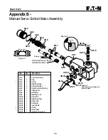
Item
Qty.
Description
8-1
9
Piston assemblies
8-2
1
Shoe Retainer
8-3
1
Shoe Retainer Pivot
8-4
1
Retainer
8-5
1
Cylinder Barrel
8-6
3
Pins
8-7
2
Washer
8-8
1
Spring
8-9
1
Retaining Ring
8-1
8-2
8-3
8-5
8-4
8-6
8-7
8-8
8-9
8-7


