21
EATON
Series 1 Heavy Duty Hydrostatic Fixed Displacement Motors Parts and Repair E-MOPI-TS002-E September 2004
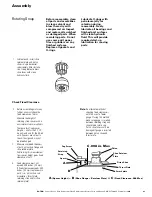
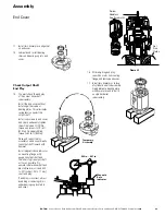
Swashplate
Thrust Plate
Piston Shoe
Spacer
Retaining
Strap
Cap Screw
Piston
Shoe Retainer
Plate
A
B
C .008 in. Max
A
(Spacer Height)
– B
(Shoe Retainer Plate)
= C
(Fixed Clearance .008 Max)
2. Before assembling motor any
further, you must check the
fixed clearance of motor.
Measure the height of
retaining strap spacer with a
micrometer or vernier calipers.
There are two fixed spacer
heights – one for the 33, 39,
46 units and one for the 54, 64
units. Spacers are critical to
the unit design and may not
be interchanged.
3.
Measure combined thickness
of both piston shoe flange and
shoe retainer plate.
Subtracting this measurement
from spacer height gives fixed
clearance of unit.
4.
Fixed clearance must not
exceed .008 inches [,20 mm].
If fixed clearance exceeds .009
inches [,02 mm], replace worn
parts, (i.e., piston shoe sub-
assemblies, thrust plate,
retaining strap and/or shoe
retainer plate).
1. Lubricate and install shoe
retainer plate and piston
shoes in cylinder barrel
subassembly. After installa-
tion, freely lubricate brass
shoe faces with clean
hydraulic fluid.
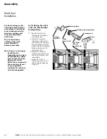
Rotating Group
Before reassembly, clean
all parts and assemblies
in clean solvent and
blow them dry with
compressed air. Inspect
and replace all scratched
or damaged parts. When
reworking parts. Do not
use coarse grit paper,
files or grinders on any
finished surfaces.
Replace all gaskets and
O-rings.
Lubricate O-rings with
petroleum jelly for
retention during
reassembly. Freely
lubricate all bearings and
finished part surfaces
with clean hydraulic
fluid. This will provide
required start-up
lubrication for moving
parts.
Note:
An alternate method of
checking fixed clearance is
with the use of a feeler
gauge. If using this method,
make sure gauge is inserted
between retaining strap and
shoe retainer plate only.
Piston shoe faces could be
damaged if gauge is inserted
between piston shoe and
thrust plate.
Check Fixed Clearance
Assembly


