background image

Copyright © 2009-2012 Eagle Tree Systems, LLC 


http://www.eagletreesystems.com 


Main Screen 


       Instruction Manual for OSD Pro 

                             Document Version 4.7 
 
               Corresponds to Eagle Tree Software  
                          Version 10.43 or higher 


Introduction 

Thank you for your purchase!   This instruction manual will guide you through the installation 
and operation of your OSD Pro.  
 
The latest version of this manual is available in the Product Manuals section of the Support 
tab on 

http://www.eagletreesystems.com

. The online manual includes any updates that were 

made after your CD was produced.   Please read the entire manual carefully before 
proceeding
.     
 
If, after you read the manual, you have further questions or problems, see the “Have 
Questions or Feedback?” section below. 
 

Intended Uses 

The OSD Pro is intended to be used exclusively for recreational purposes in model 
planes, boats and cars.   Any other use is not supported. 


What is FPV?    
 
If you are not familiar with FPV, there are many websites devoted to it.   Our FPV 
overview web page at 

http://www.eagletreesystems.com/OSD


has a brief tutorial on 

FPV, which is a good place to start.


Quick Start Guide 

We recommend that most customers start with basic OSD Pro setup, and then proceed 
as desired to use more advanced features.   A Quick Start Guide, which supplements 
this manual, is included with your product.    The latest version of the quick start guide 
is available in the Product Manuals section of the Support tab on 

http://www.eagletreesystems.com

 
Packing List 

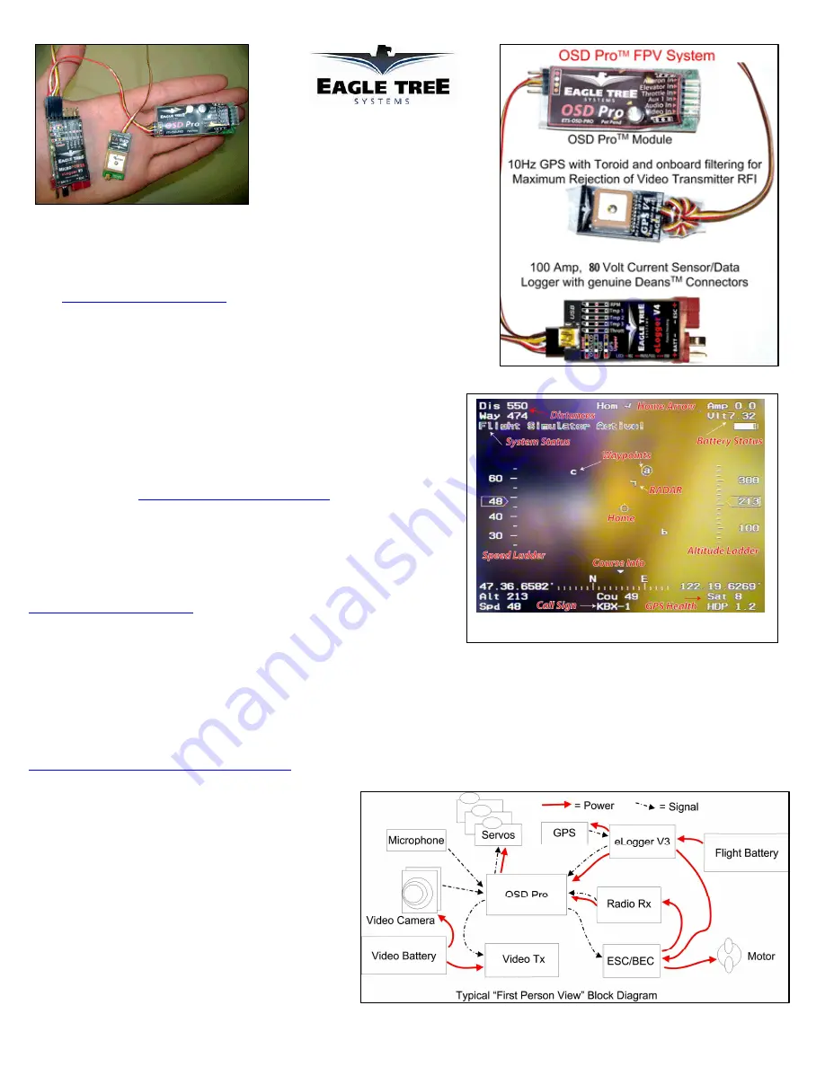
Your package should include the following:  The OSD Pro, and five (5) male to male servo connectors, and a printed version of the Quick Start Guide.   
Additionally, if you purchased our complete OSD Pro package, you should have received an eLogger V4, and a GPS Module.  Note that an eLogger V4, 
eLogger V3, or Data Recorder is required for system operation, and our GPS module is recommended.   Additionally, our Guardian Stabilization Expander 
is available to provide stabilized flight and additional features. 
 
Other Things You Need 
To utilize the OSD Pro system, you will need (at a minimum) a video camera and video transmitter on your model, and a video receiver and video display on 
the ground.   Many of our dealers also sell video equipment.  A list of FPV specific dealers can be found on our website at 

http://www.eagletreesystems.com/OSD/OSD-Pro.htm

 
What the OSD Pro Does


The OSD Pro is a powerful, modular, fully configurable 
Video/Audio On-Screen Display (OSD) device, providing 
graphics, voice announcements, alarms, acoustic variometer with 
total energy compensation, Home Arrow, Artificial Horizon, 
Return to Home, Failsafe, “RADAR”, waypoints, flight timer, 
flight summary,  saving and graphing your flight data (including 
all sensor data),  Google Earth data display, a flight simulator for 
testing, and many other features.    The information displayed can 
be as simple or advanced as you like, depending on how you 
configure the display, and on which optional Eagle Tree sensors 
are connected. 
 
To use your OSD Pro, you need the OSD Pro Expander, and the 
eLogger V4/V3 or Data Recorder.   To make full use of the OSD 

Содержание OSD pro

Страница 1: ...p www eagletreesystems com Packing List Your package should include the following The OSD Pro and five 5 male to male servo connectors and a printed version of the Quick Start Guide Additionally if yo...

Страница 2: ...ly recommended that you set the Capture Rate of your eLogger or Recorder to 10 samples second for best OSD Pro update rate and performance 6 Install and configure the OSD Pro as described below Note t...

Страница 3: ...our flight automatically For more information see the Display Live or Max Values on screen menu item description in the Main Menu table under the Description of On screen Menus section of the manual b...

Страница 4: ...perature input connects to probe Note that this configuration assumes a common ground exists between the eLogger and each additional battery to be measured In most cases ground is already shared This...

Страница 5: ...am also known as PPM sum you may be able to connect your OSD Pro to your Receiver with only one male to male servo connector See the Serial PPM section in the manual below for more information Tips fo...

Страница 6: ...e a PowerPanel or other sensors those can daisy chain to the pins on the OSD Pro with the polarity as indicated on the OSD Pro label as shown in Figure 2 The GPS Expander connects to the upper row of...

Страница 7: ...ay to connect the video camera and video transmitter using a servo Y cable Note that the camera and transmitter MUST be able to operate at the same voltage to use the this diagram Connecting the OSD P...

Страница 8: ...nputs to your receiver The OSD Pro is connected to your receiver via the included male to male servo connectors The Futaba end of each connector plugs into the OSD Pro and the Universal JR end plugs i...

Страница 9: ...figuration File AFTER you have installed the new software version and completed the OSD Pro firmware update if prompted to do so Configuring Text Parameters to Display on the Video OSD A powerful and...

Страница 10: ...lert you of potential problems before they become serious There are 3 ways that the OSD Pro can alert you if a parameter has reached its trigger level 1 The parameter is displayed in reverse video on...

Страница 11: ...update if prompted to do so You can also use this feature to set up multiple OSD Pros with the same configuration rather than configuring each one separately Factory Reset The Factory Reset button er...

Страница 12: ...ivated is the same as setting the RTH test mode to both in the menus but is easier to access RTH test mode will be active until the control surfaces are moved RTH will release briefly when this happen...

Страница 13: ...nnel will turn the OSD Pro on and off To advance between multiple pages just click the Select channel for Option B just toggle the 3 position switch between the up and middle positions Note that when...

Страница 14: ...h 3 shows lots of change in the percentage readout that indicates that channel 3 of the serial PPM stream controls the throttle So you would select Channel 3 for the Throttle dropdown menu Each OSD Pr...

Страница 15: ...ltitude is less than 60 feet 20 meters above ground level or if your speed is less than 3 MPH or 3K H note that the low altitude check can be disabled via the menus as described below If you routinely...

Страница 16: ...ottle will shut the engine off which will make RTH much less useful An added benefit of using the throttle trim to set the failsafe position is that you can test RTH in flight by trimming the throttle...

Страница 17: ...to Yes it causes the OSD Pro to skew the servo pulses in RTH mode Unfortunately this causes the voice announcements to automatically be turned off during RTH mode including the signal lost announceme...

Страница 18: ...tor down position when it attempts to climb or descend the model So the amount of down stick you supply will set the maximum throw of the elevator during RTH Set your Throttle stick for Descending nor...

Страница 19: ...mporarily this can make testing easier b Recommended If you have set up your electric model s throttle failsafe as described in the Setting up RTH with Receivers that Support a Throttle Failsafe secti...

Страница 20: ...itude to well above the Cruise Altitude Window Then release the sticks Once RTH mode engages you should begin to see a decrease in altitude until the altitude reaches the Cruise Altitude Window 18 If...

Страница 21: ...n roll gain values move the ailerons or rudder too much you may need to decrease the Turn Proportional Limit parameter 16 If the model turns at a reasonable rate but overshoots the turn when the model...

Страница 22: ...ervos if you turn off your radio the servos no longer are held in one position and or start moving randomly PCM FS this option should be chosen if your receiver holds the last servo position or goes i...

Страница 23: ...Cruise Altitude is set to 300 and Altitude Error was set to 100 the Cruise Altitude Window would be between 200 and 400 Never set this value so that this value when added to Cruise Altitude parameter...

Страница 24: ...lets you adjust the horizontal position of the OSD data on your video screen Increasing this parameter causes the OSD data to shift rightward on the screen Set Vertical Screen Shift This setting lets...

Страница 25: ...this maximum radius they will be displayed in reverse video Flight Timer Elapsed Time Set this to YES to enable the Flight Timer which appears in the upper left hand corner when enabled The Flight Tim...

Страница 26: ...hich changes as you ascend or descend at different rates When ascending the tone will be broken with the tone frequency increasing as the rate of ascent increases When descending the tone will be cont...

Страница 27: ...from normal video to reverse video to indicate you are out of range Likewise if Set Minimum Satellite Count Set this to a non zero value if you wish to specify the minimum number of satellites that mu...

Страница 28: ...more information Set Voltage C Minimum This menu item lets you set the minimum voltage for the secondary graphical battery voltage B display The graphical battery C will show empty when this voltage...

Страница 29: ...Ensure that the eLogger V3 or Recorder is connected correctly to USB The LED should flash a sequence of three repeating blinks if it is correctly connected Ensure that you have updated the eLogger re...

Страница 30: ...omatically detected Parameters Displayed Limited only by the sensors you have purchased Character Graphic Display Type High contrast white with black character outline for optimum visibility Number of...

Отзывы: