background image

E-Tech W 

: 664Y6500 • B

en

8

EN

FR

NL

ES

IT

DE

PL

RU

TECHNICAL CHARACTERISTICS

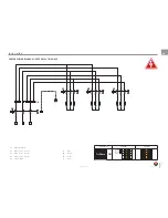
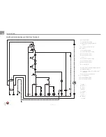
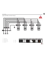
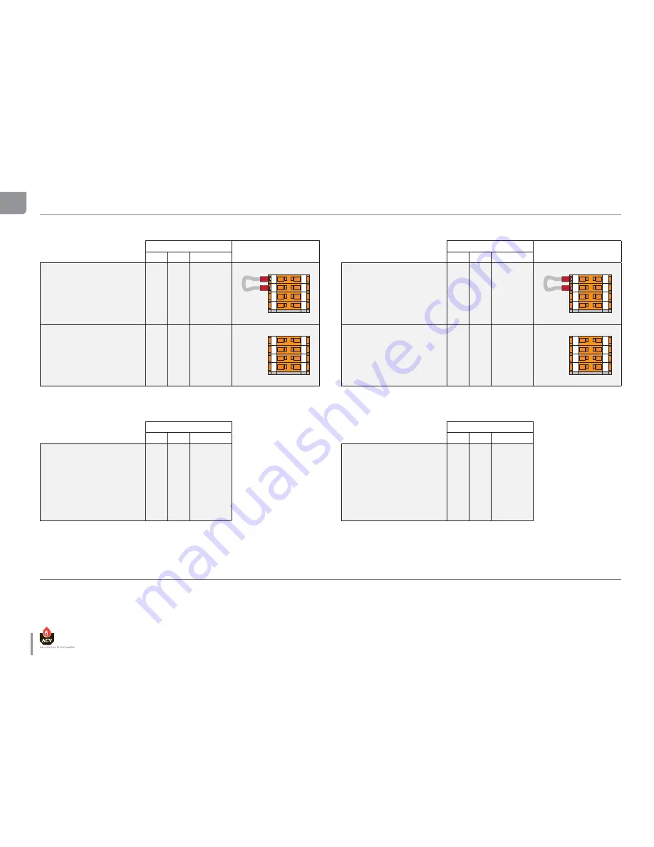
ELECTRIC DATA OF MODEL 09 SINGLE PHASE

STAGE

CONTROL TERMINALS

1

2

TOTAL

Single Phase 8.4 kW (*)

12

12

13

13

14

14

15

15

Terminal L1 

(A)

24

12

36

Terminal N 

(A)

24

12

36

Power

(kW)

5.6

2.8

8.4

Single Phase 5.6 kW (**)

12

12

13

13

14

14

15

15

Terminal L1 

(A)

12

12

24

Terminal N 

(A)

12

12

24

Power

(kW)

2.8

2.8

5.6

ELECTRIC DATA OF MODEL 15 SINGLE PHASE

STAGE

CONTROL TERMINALS

1

2

TOTAL

Single Phase 14.4 kW (*)

12

12

13

13

14

14

15

15

Terminal L1 

(A)

41.6

20.8

62.4

Terminal N 

(A)

41.6

20.8

62.4

Power

(kW)

9.6

4.8

14.4

Single Phase 9.6 kW (**)

12

12

13

13

14

14

15

15

Terminal L1 

(A)

20.8

20.8

41.6

Terminal N 

(A)

20.8

20.8

41.6

Power

(kW)

4.8

4.8

9.6

ELECTRIC DATA OF MODEL 09 TRI PHASE

STAGE

1

2

TOTAL

Tri Phase 8.4 kW

Terminal L1 

(A)

6

6

12

Terminal L2

(A)

6

6

12

Terminal L3 

(A)

6

6

12

Power

(kW)

4.2

4.2

8.4

ELECTRIC DATA OF MODEL 15 TRI PHASE

STAGE

1

2

TOTAL

Tri phase 14.4 kW

Terminal L1 

(A)

10.4

10.4

20.8

Terminal L2

(A)

10.4

10.4

20.8

Terminal L3 

(A)

10.4

10.4

20.8

Power

(kW)

7.2

7.2

14.4

This values are based on standard supply voltage in Europe, that is 1 x 230V for single phase and 3 x 400 Volt for tri phase.
  (*)  Factory configuration.
  (**)   Remove the shunt 12 and 13 on control wiring in order to deactivate the relay.
 (***)   Remove the shunt 14 and 15 on control wiring in order to deactivate the relay.

Содержание E-Tech W 09

Страница 1: ...664Y6500 B EN FR NL ES IT DE PL RU INSTALLATION OPERATION AND MAINTENANCE INSTRUCTIONS 09 15 22 28 36 Single Tri Phase...

Страница 2: ...mensions 10 Installation room 10 Disassembling 11 Heating connection 12 Heating connection dHW Y PLAN 12 Heating connection dHW S PLAN 12 Connecting the power supply 13 Connecting the electrical Acces...

Страница 3: ...ommend that the boiler be handled by two people until it is securely fixed to a wall The safest route from the vehicle to the point of installation should be carefully assessed before unloading the bo...

Страница 4: ...low direct connection to a heating system without the need for a feed and expansion cistern These components include primary 10 litre expansion vessel suitable for a system water content of up to 160...

Страница 5: ...FR NL ES IT DE PL RU INTRODUCTION LEGEND 1 Relay 2 Timer 3 Control terminals 4 Circuit breaker 5 Safety switch 6 Power terminals with fuse 25A or 32A 7 Power terminals E Tech W 09 15 Single Phase E T...

Страница 6: ...ng normal boiler operation depending on boiler temperature If the boiler is not in regular daily use during cold periods it is recommended that it be fitted with a frost sensing thermostat to override...

Страница 7: ...working pressure bar 3 Min working pressure bar 0 8 Max working temperature C 87 Hydraulic pressure drop E Tech W 09 Single Tri mbar 10 E Tech W 15 Single Tri mbar 20 E Tech W 22 Tri mbar 45 E Tech W...

Страница 8: ...14 4 Single Phase 9 6 kW 12 12 13 13 14 14 15 15 Terminal L1 A 20 8 20 8 41 6 Terminal N A 20 8 20 8 41 6 Power kW 4 8 4 8 9 6 ELECTRIC DATA OF MODEL 09 TRI PHASE STAGE 1 2 TOTAL Tri Phase 8 4 kW Term...

Страница 9: ...al L3 A 20 8 20 8 41 6 Power kW 14 4 14 4 28 8 Tri phase 21 6 kW 12 12 13 13 14 14 15 15 Terminal L1 A 20 8 10 4 31 2 Terminal L2 A 20 8 10 4 31 2 Terminal L3 A 20 8 10 4 31 2 Power kW 14 4 7 2 21 6 E...

Страница 10: ...suitable external frost thermostat should be fitted CONNECTING TO THE SYSTEM the boiler is designed to operate on a sealed system ie no open vent or feed and expansion cistern Hot water expansion with...

Страница 11: ...DISASSEMBLING Panel removal and access to hydraulic connections 1 Undo screws 2 Tilt panel towards you and lift clear remove the top cover 3 Loosen screws of the control panel 4 Turn up the control pa...

Страница 12: ...9 2 8 27 26 25 24 23 2 2 2 1 1 9 40 2 0 1 8 17 16 15 14 13 1 2 1 1 9 3 0 1 0 8 7 6 5 4 3 2 1 3 9 3 8 37 36 35 34 33 3 2 3 1 2 9 2 8 27 26 25 24 23 2 2 2 1 1 9 40 2 0 1 8 17 16 15 14 13 1 2 1 1 9 3 0 1...

Страница 13: ...0 Hz en 13 E Tech W 664Y6500 B EN FR NL ES IT DE PL RU INSTALLATION CONNECTING THE POWER SUPPLY This appliance must be permanently connected to fixed wiring and must be earthed The wiring must be carr...

Страница 14: ...or controller supply optional 3 4 DHW kit optional 5 6 Stop Bridge or time clock switch control optional 7 8 Room thermostat optional 9 10 11 Heating pump 12 13 Relay K3 deactivated 1 2 Time clock or...

Страница 15: ...insulation the wires canalisation the mounting and the environment The following values are given for information for an ambient temperature of 30 C and a maximal length of 5 meters In all the cases t...

Страница 16: ...H W 09 15 SINGLE PHASE CB Circuit breaker S1 ON OFF switch lamp S2 Manual reset safety thermostat 103 C PS Low water pressure switch DS1 Alarm S3 Control thermostat S4 Power switch level 1 lamp K1 Pow...

Страница 17: ...DE PL RU INSTALLATION POWER WIRING DIAGRAM E TECH W 09 15 SINGLE PHASE E Tech W 09 8 4 kW 5 6 kW Single Phase TB1 12 12 13 13 14 14 15 15 12 12 13 13 14 14 15 15 E Tech W 15 14 4 kW 9 6 kW Single Phas...

Страница 18: ...IRING DIAGRAM E TECH W 09 15 TRI PHASE CB Circuit breaker S1 ON OFF switch lamp S2 Manual reset safety thermostat 103 C PS Low water pressure switch DS1 Alarm S3 Control thermostat S4 Power switch lev...

Страница 19: ...k R Or Bk R Or B B B B B B Bk R Or Bk R en 19 E Tech W 664Y6500 B EN FR NL ES IT DE PL RU INSTALLATION POWER WIRING DIAGRAM E TECH W 09 15 TRI PHASE S6 Power terminals K1 Power relay 1 level 1 K2 Powe...

Страница 20: ...TECH W 22 TRI PHASE CB Circuit breaker S1 ON OFF switch lamp S2 Manual reset safety thermostat 103 C PS Low water pressure switch DS1 Alarm S3 Control thermostat S4 Power switch level 1 lamp K1 Power...

Страница 21: ...Bk R R en 21 E Tech W 664Y6500 B EN FR NL ES IT DE PL RU INSTALLATION POWER WIRING DIAGRAM E TECH W 22 TRI PHASE E Tech W 22 21 6 kW 14 4 kW Tri Phase TB1 12 12 13 13 14 14 15 15 12 12 13 13 14 14 15...

Страница 22: ...SE CB Circuit breaker S1 ON OFF switch lamp S2 Manual reset safety thermostat 103 C PS Low water pressure switch DS1 Alarm S3 Control thermostat S4 Power switch level 1 lamp K1 Power relay 1 level 1 K...

Страница 23: ...Tech W 664Y6500 B EN FR NL ES IT DE PL RU INSTALLATION POWER WIRING DIAGRAM E TECH W 28 TRI PHASE E Tech W 28 28 8 kW 21 6 kW 14 4 kW Tri Phase TB1 12 12 13 13 14 14 15 15 12 12 13 13 14 14 15 15 12 1...

Страница 24: ...SE CB Circuit breaker S1 ON OFF switch lamp S2 Manual reset safety thermostat 103 C PS Low water pressure switch DS1 Alarm S3 Control thermostat S4 Power switch level 1 lamp K1 Power relay 1 level 1 K...

Страница 25: ...R R en 25 E Tech W 664Y6500 B EN FR NL ES IT DE PL RU INSTALLATION POWER WIRING DIAGRAM E TECH W 36 TRI PHASE E Tech W 36 36 kW 27 kW 18 kW Tri Phase TB1 12 12 13 13 14 14 15 15 12 12 13 13 14 14 15 1...

Страница 26: ...7 8 9 10 V4043H DHW ZONE VALVE MOTOR Honeywell Sundial Wiring Centre S Plan Note Earth wires not shown for clarity During installation the earth wires from each component connect to terminal 3 in the...

Страница 27: ...wires from each component connect to terminal 3 in the wiring centre bk black br brown r red w white y yellow o orange b blue v violet p pink gr grey CABLE COLOUR CODES gr b b b o 1 2 C HW OFF V4073A...

Страница 28: ...stage 1 the first stage contactors will energise 6 Switch on the power levels switch stage 2 after a short delay the second stage contactors will energise Note the power stage delay timer settings sh...

Страница 29: ...en 29 E Tech W 664Y6500 B EN FR NL ES IT DE PL RU REMOVAL THE HEATING ELEMENTS 3 1 2...

Страница 30: ...E Tech W 664Y6500 B en 30 EN FR NL ES IT DE PL RU...

Отзывы: