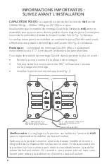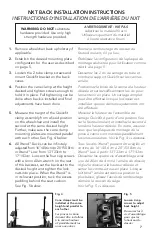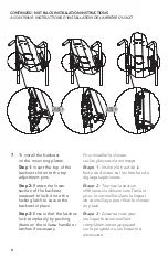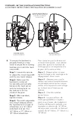
15
3. Head Rest Mounting
The Upper and Middle segments
of the Armadillo shell have slots
to accept mounting hardware
for the nxt MultiFit Head Rest.
Choose the location which
provided the best positioning for
the head rest.
Support de tête
Support de tête Les segments supérieur
et central de la coque Armadillo ont
des fentes pour accepter le matériel de
montage pour le repose-tête MultiFit
de nxt. Choisissez l’emplacement qui a
fourni le meilleur positionnement pour
le repose-tête.
4. Lateral Installation and
Adjustment
Upper laterals are held in place
by screws B and the lower laterals
by screws E. These screws thread
into sliding nuts in slots on the
laterals allowing the laterals to be
infinitely adjustable between their
most inner and outer positions
only limited by the postural
requirements of the occupant of
the wheelchair and any structural
components of the wheelchair.
Loosening screws B or E allowing
the laterals to slide will not affect
the positioning of the mounting
hooks.
Installation et réglage latéraux
Les latéraux supérieurs sont
maintenus en place par les vis B
et les latéraux inférieurs par les
vis E. Ces vis se vissent dans les
écrous coulissants dans les fentes
latérales, ce qui permet de régler les
latéraux entre leurs positions les plus
internes et externes uniquement en
fonction des exigences posturales de
l’occupant du fauteuil roulant et des
composants structurels du fauteuil
roulant. Desserrer les vis B ou E en
faisant glisser les latéraux n’affectera
pas le positionnement des crochets
de montage.
CANAL
CENTRAL
B
B
E
E
UPPER
LATERAL
UPPER
LATERAL
LOWER LATERAL
WITH LARGE PAD
LOWER LATERAL
WITH LARGE PAD
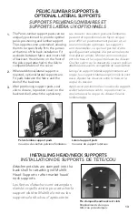
3. Head Rest Mounting
The Upper and Middle segments of the MAPS shell have slots to accept mounting hardware
for the nxt MultiFit Head Rest. Choose the location which provided the best positioning for
the head rest.
FRONT VIEW
20°
40°
30° 30°
UPPER SEGMENT
LOWER SEGMENT
G
F
HINGE JOINT
HINGE JOINT
4. Lateral Installation and Adjustment
Upper laterals are held in place by screws B and the Lower laterals by screws E. These
screws thread into sliding nuts in slots on the laterals allowing the laterals to be infinitely
adjustable between their most inner and outer positions only limited by the postural
requirements of the occupant of the wheelchair and any structural components of the
wheelchair. Loosening screws B or E allowing the laterals to slide will not affect the
positioning of the mounting hooks.
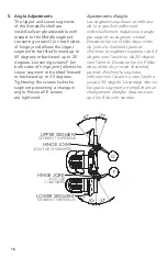
5. Angle Adjustments
The Upper and Lower segments of the MAPS
shell are individually angle adjustable with
respect to the Middle segment. Loosening
screws G (on both sides of hinge joint) allows
the Upper segment to be tilted forward up to
40 degrees or backward up to 20 degrees.
Loosening screws F (on both sides of hinge
joint) allows the Lower segment to be tilted
forward or backward up to 30 degrees.
Tightening the screws locks the segment
preventing a change in angle. Ensure all 8
screws are tightened.
LATERAL
SUPÉRIEUR
LATERAL
SUPÉRIEUR
VUE DE FACE
BAS LATERAL AVEC
GRANDCOUSSIN
BAS LATERAL AVEC
GRANDCOUSSIN
B
B
E
E
UPPER
LATERAL
UPPER
LATERAL
LOWER LATERAL
WITH LARGE PAD
LOWER LATERAL
WITH LARGE PAD
3. Head Rest Mounting
The Upper and Middle segments of the MAPS shell have slots to accept mounting hardware
for the nxt MultiFit Head Rest. Choose the location which provided the best positioning for
the head rest.
FRONT VIEW
20°
40°
30° 30°
UPPER SEGMENT
LOWER SEGMENT
G
F
HINGE JOINT
HINGE JOINT
4. Lateral Installation and Adjustment
Upper laterals are held in place by screws B and the Lower laterals by screws E. These
screws thread into sliding nuts in slots on the laterals allowing the laterals to be infinitely
adjustable between their most inner and outer positions only limited by the postural
requirements of the occupant of the wheelchair and any structural components of the
wheelchair. Loosening screws B or E allowing the laterals to slide will not affect the
positioning of the mounting hooks.
5. Angle Adjustments
The Upper and Lower segments of the MAPS
shell are individually angle adjustable with
respect to the Middle segment. Loosening
screws G (on both sides of hinge joint) allows
the Upper segment to be tilted forward up to
40 degrees or backward up to 20 degrees.
Loosening screws F (on both sides of hinge
joint) allows the Lower segment to be tilted
forward or backward up to 30 degrees.
Tightening the screws locks the segment
preventing a change in angle. Ensure all 8
screws are tightened.


