


20
shims stacked to make up the thickness required. De- burr
shim edges.
Vertical flange mounted drives require shims inserted
between the flange faces. Use the following procedure
when placing shims to avoid twisting the flange. De-burr
shim edges and use as few thick shims as possible
instead of many thin shims. See Figure 3-4.
1. Determine thickness of shim needed to correct
angular alignment by calculation or trial and error.
This shim is placed on the flange face at the point
where the smallest misalignment reading was taken.
2. Shim should not be wider than the distance from the
outer flange edge to the bolt circle of the hold down
bolts and the length should be twice the width. Notch
for bolt.
3. Cut two additional shims the same size but one half
the thickness and place them 90º from the thick shim,
on either side. Notch to clear hold down bolts, if
necessary.
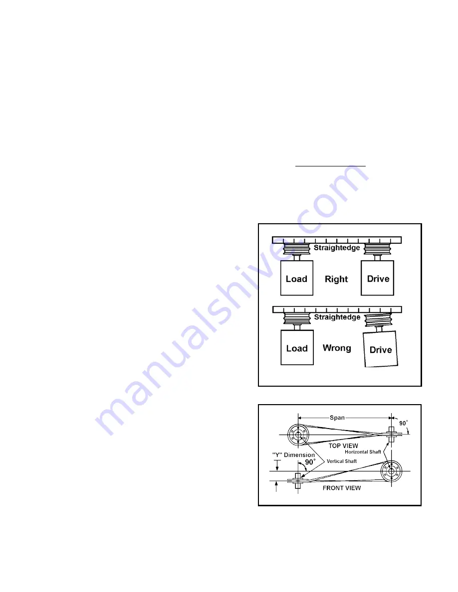
Parallel Connected Shafts
Parallel shafts must be aligned to prevent excessive
thrust loads on the unit's shaft and to minimize belt or
chain wear. To check parallel shaft alignment, simply
place a straightedge across the faces of the two sheaves
or sprockets as shown in Figure 3-5. When properly
aligned, the straightedge should contact the faces of both
devices squarely. The object is to have the belt leave or
enter the groove without rubbing or thrusting against the
side of the groove.
Quarter-twist belts are often used to transmit power
between a horizontal and vertical shaft. These shafts
must be perpendicular and aligned as shown in Figure 3-
6 to minimize bell wear and bearing loads. When looking
down, as shown in the top view, a line perpendicular to
the horizontal sheave at the center of its sheave must
pass through the center of the vertical shaft. When looking
at the end of the horizontal shaft, as shown in the front
view, a line perpendicular to the vertical shaft at the center
of its sheave must pass a distance "Y" below the center
of the horizontal shaft.
Belt Tension
Belt and chain drives are tensioned by sliding the unit
sideways after loosening the hold down bolts. It is very
important to establish the proper tension, which is one just
above the point of slippage. Belts that are too loose will
slip, preventing proper acceleration or full output speed
while creating belt overheating and pulley grove wear. On
the other hand, tightening the belt or chain more than is
necessary increases wear of the belt, bearings and shaft.
When available, follow the belt manufacturer's
instructions for optimum tensioning. When such
instructions are not available and the belt and sheave are
not sized marginally, a simple check may be made to
determine belt tension. To perform this check, place
thumb on belt at a point midway between the two
sheaves and press downward. The belt should deflect a
distance equal to one-half of its thickness for each 24
inches of distance between the sheaves.
Because the simple check described above is not very
precise, it is not recommended when the sheave is at or
near the minimum size permitted by the unit's overhung
load capacity. In such cases, even slight over-tightening
of the belts can cause serious damage. To avoid these
problems, check tension of marginally sized belts or
sheaves with a belt tension gauge following the directions
furnished with the gauge, or use the following procedure:
1. Calculate the value for a test weight or deflection
pressure using the following formula:
Weight (Lbs.) = (OHL x Pf x 0.03125) +Mf
No. of belts used
Where:
OHL = Overhung load capacity of shaft in pounds.
Obtain from engineering data tables in section
2 of this manual. Contact your local sales
office for configurations that are not listed.
Parallel Shaft Alignment
Figure 3-4
Perpendicular Shaft Alignment
Figure 3-5