


18
4. If unit has been stored outdoors and especially in
humid climates, check for condensation and water
damage to insulation and bearings.
5. Make sure accessory equipment is complete and
undamaged. Movable devices should be operated to
determine if they function freely and correctly.
Correct any deficiency and remove dirt, rust and
protective coatings. Use a safe solvent to clean shaft,
flange face and mounting feet. Remove burrs with a fine
file or scraper. Do not use emery cloth, sandpaper or any
other abrasive.
Sizing Sheaves and Sprockets (Overhung Load)
Before a sheave or sprocket is installed on the shaft,
make sure it does not exceed the minimum diameter
limitation. This is a limitation established by the
overhung load capacity of the unit. Too small a sheave
may result in early bearing failure or a broken shaft.
Calculate the minimum sheave diameter using the
following formula:
(126,000 x HP x Lf x Tf)
PD min. =
(OHL x Pf x RPM)
Where:
PD min. = Minimum pitch diameter, in inches.
HP = Rated horsepower of clutch from clutch nameplate.
Lf
= Load factor of clutch is a ratio of maximum
expected load to rated load, usually at least a
factor of 1.5. See Table 3-2.
OHL = Overhung load capacity of shaft in pounds. Obtain
from Section 2 of this manual. Contact your
local sales office for configurations that are
not listed.
Tf
= Tension factor for type of bell drive used.
See Table 3-3.
Pf
= Position factor, a factor, used to correct
overhung load capacity when the center of
belt pull is not on the center of the shaft
keyway extension. Location "L” is on the
center of keyway. See Table 3-4 and Figure
3-1.
The pitch diameter of the sheave or sprocket must be
equal to or larger than the minimum calculated. When a
smaller diameter must be used, mount the pulley on a
separate jackshaft, supported by separate bearings. Align
the jackshaft to the unit's shaft as described for directly
connected shafts.
The overhung load ratings listed in Section 2 are for units
with a standard-length output shaft and either standard
output ball bearing or optional/standard output spherical
roller bearing, as indicated in the tables. Units with an
external brake have a longer shaft. Separate overhung
load rating tables are provided for units with a brake.
For non-standard models, contact
DSI/Dynamatic® to obtain the overhung load rating. To
determine if your unit is standard, compare its dimensions
(shaft length) and the model number imprinted on its
nameplate with the model numbers and engineering data
tables in Section 2 of this manual.
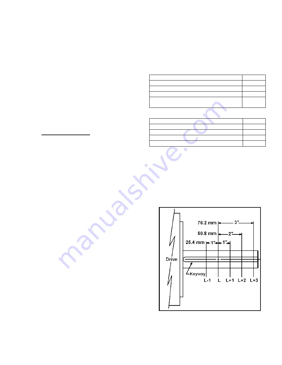
Note that OHL is in pounds force at the center of the shaft
keyway. Positioning the pulley so the center of belt pull is
not at the center of the keyway changes the OHL capacity.
Table 3-4 lists the Position Factors used to correct the
OHL. Factors are provided for 1 inch closer to the bearing
(L-1); and 1 inch (L+1), 2 inches (L+2) and 3 inches (L+3)
further away from the bearing. If belt center is on the
keyway center, Position Factor L is 1.0.
Load Factors
Table 3-2
Type of Load
Lf
Load never exceeds full load
1.00
Load sometimes equals 125% of full load
1.25
Normal loads
1.50
Occasional loads equal to 200% of full
load
2.50
Tension Factors
Table 3-3
Tension Factors
Tf
Chain and sprocket
1.00
Pinion or gear
1.25
V-belt and sheave
1.50
Flat belt and pulley
2.50
Installing Sheaves, Sprocket or Couplings
Coupling halves, sheaves, sprockets or gears should be
installed on the shaft before mounting the unit. Before
installing these hubs on the shaft, inspect the shaft and its
key. Remove any burrs using a fine file. Do not use emery
cloth or other abrasives. Also, be sure the key fits snugly
to the sides of the keyways on both the shaft and device
hubs. Some clearance between the top of the key and the
hub keyway is acceptable and will make installation
easier.
Locating Position Factors
Figure 3-1
On Standard Shafts
Generally, the device should be installed on the shafts by
following the device manufacturer's instructions. Devices
with split hubs or light interference fits that use