


- 7 -
For average Amateur installations for 1.8 to 30 MHz intermittent
operations, where the DC supply is normally turned off, standard
internal bias tee DC over the RF coax is perfectly acceptable.
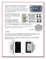
The internal three-pin jumper headers
J2 BT
and
J3 EXT DC
, located
next to the PC board F connector terminals, are used to select the DC
power for the AVA-3.
Both headers require identically jumpered
pins in order to function.
The Default setting as supplied is with both
pins 1 and 2 are connected together (jumpers
installed) on both J2 and J3 headers, the bias
tee provides power from the “
75 Ω OUTPUT
”
coax F connector.
When pins 2 and 3 are connected together
(jumpers installed) on both headers, the
separate “
OPTIONAL DC POWER
” F
connector supplies DC power to the AVA-3
circuitry. In that case the center pin of the coax
is +13.8 VDC and the shield ground is 0 VDC. When this method of powering the
AVA-3 is chosen, the “
75 Ω OUTPUT
” coax F connector handles only the received
RF.
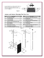
When the jumpers are set, replace the cover ensuring the weep holes are toward the
bottom (AVA-3 is mounted vertically as shown above).
Weep holes
Assembly
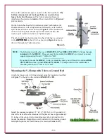
The assembly described is for a single
DXE-RSEAV-1
. Use
JTL-12555 - Jet-Lube SS-30
on the joints
between the antenna elements and on all stainless steel hardware threads to prevent galling and to ensure
proper torque.
NEVER use SS-30 or any anti-seize on RF coaxial connectors.
Orient the black mounting plate with the antenna mounting holes close to the top, as shown in
Figure 1
.
Mount the
AVA-3
matching unit using the 1" hex head bolts, flat washer under each bolt, flat and split
washer under each hex nut.
Figure 1


