DX Engineering DXE-AVA-3 Скачать руководство пользователя страница 12

- 12 - 

Providing a Good RF Ground 


This Active Vertical Antenna works well with just a single copper ground rod used as the mounting 
rod. 
 
You can test the quality of the ground when using only one ground rod.  Tune in an AM or low band 
steady signal that is not Skywave and note the signal level. Then, attach 15 feet of wire to the ground 
terminal or ground rod, laid out in a straight line away from the coaxial feedline. If you observe a 
change in signal or noise level, you need to improve the grounding.  
 
A second rod spaced a few feet away from, and connected to the first one should correct the 
problem. If a good ground cannot be established, use a 

DXE-RFCC-1 

Feedline Current Choke that 

will further decouple the feedline from the antenna and reduce common mode current and associated 
noise from the feedline. 
 
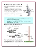
If you locate your ground mounted antenna where ground rods cannot be used effectively, you must 
use a radial system. A suitable radial system consists of four, eight or twelve equally spaced radials, 
with each radial being at least 15 feet long, but not longer than 20 feet.   
 
Only if the antenna is located over rock, on a roof, or otherwise installed where conductive soil 
conditions do not exist, you must use a ground screen. Welded-wire galvanized screens are okay for 
this receive antenna only and are not recommended for transmit antennas. Screen radius must at least 
equal the element height and be placed around the antenna as symmetrically as possible, but should 
not exceed a radius of 20 feet. The AVA-3 negative terminal or its radial system should never be 
connected to any metal structure, to assure low noise operation. 
 
Do not use elevated radials or grossly asymmetrical radial configurations. The ground system is an 
integral part of this receiving system, and if it is asymmetrical or exhibits pronounced resonances, 
the antenna system may not function properly. For multiple RSEAV Antennas used in an array, each 
element must have the identical number of ground rods and radials, if used.  
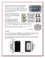
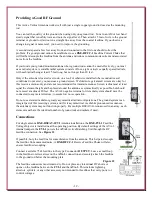
 

Connections


For single antenna 

DXE-RSEAV-1FVI

 Antenna installations, the

 DXE-FVI-1 

Feedline 

Voltage Injector is installed near the operating position. By default settings of the AVA-3 
internal jumpers, the 

FVI-1

 powers the 

AVA-3

 Active Matching Unit through the RF 

feedline connection. See 

Figure 12

.  

 
If possible, bury the feed line for some distance from the antenna. This helps to decouple 
the feedline from unwanted noise. A 

DXE-RFCC-1

 Receive Feedline Choke will also 

ensure feedline decoupling.  
 
Connect a suitable 75 Ω feedline to the type F connector 

OUTPUT

. Leave a small loop 

in the feedline to relieve stress on the 

AVA-3

 connection and securely attach the feedline 

to the ground rod below the mounting plate. 

Figure 12 


The feedline connectors must remain dry. Do not place any intentional DC shorts or 
opens on the feedline between the 

FVI-1

 and the 

AVA-3

. This includes lightning 

arrestors, splitters, or any other accessory not intended for feedlines that carry power or 
control voltages.  
 

Содержание DXE-AVA-3

Страница 1: ...EAV 1FVI Single Active Vertical Antenna w Feedline Voltage Inserter DXE RSEAV INS Revision 0 DXE RSEAV 1 shown with optional ground rod DX Engineering 2022 1200 Southeast Ave Tallmadge OH 44278 USA Phone 800 777 0703 Tech Support and International 330 572 3200 E mail DXEngineering DXEngineering com ...

Страница 2: ...ts for use in phased array systems At the heart of the RSEAV Antennas is the DXE AVA 3 Active Matching Unit Its state of the art broadband operational amplifier design works as a high impedance buffer for the connection to a short element of 6 to 24 feet It achieves unparalleled weak signal reception with these features and benefits Ultimate frequency coverage of 40 kHz to 30 MHz for VLF through H...

Страница 3: ... are not broadband noise generators If the noise source is external and single directional in nature using two DXE RSEAV 1 antennas in conjunction with the DXE NCC 2 Receive Antenna Phasing Controller could allow the user to phase out the noise being received Large transmit antennas are also very good source of re radiated noise A DXE RSEAV 1 or the DXE AVA 3 cannot be mounted on or near a mast or...

Страница 4: ...ias tee and power source for use with any receiver or a transceiver with a receive antenna RX ANT input May be used on any transceiver with the optional DXE RTR 2 Modular Receive Transmit Interface DXE AVA 3 Active Matching Unit Non conductive mounting plate Aluminum 3 piece antenna element 8 feet 6 inches long DXE FVI 1 Feedline Voltage Injector powers the matching system and provides radio conne...

Страница 5: ... wrenches or nut drivers and a 5 8 wrench 2 Phillips Head Screw Driver 7 64 and 3 32 Allen Wrenches Included in this kit Knife or Scissors for cutting the weatherproofing tapes Parts needed but not included JTL 12555 Jet Lube SS 30 for antenna elements and all stainless steel hardware LCT 37534 Loctite Dielectric Grease used on F Connectors TES 2155 3M Temflex Tape used to weatherproof the F Conne...

Страница 6: ...ithin 10 miles 16 km As the gain setting is increased in the AVA 3 the possibility for RF overload and distortion increases at extremely high signal input levels Therefore in locations with multiple transmitters or high ambient local noise do not use the 6dB setting Longer elements such as 20 to 24 ft that are typically used for low band AM LF and VLF will also produce a higher ambient local and a...

Страница 7: ...ER F connector supplies DC power to the AVA 3 circuitry In that case the center pin of the coax is 13 8 VDC and the shield ground is 0 VDC When this method of powering the AVA 3 is chosen the 75 Ω OUTPUT coax F connector handles only the received RF When the jumpers are set replace the cover ensuring the weep holes are toward the bottom AVA 3 is mounted vertically as shown above Weep holes Assembl...

Страница 8: ... Socket Head Cap Screw 2 2 1 2 Tube Drilled 1 12 6 Flat Washer 2 3 3 8 Tube Drilled 1 13 6 32 Nylon Lock Nut 2 4 1 4 Tube Drilled 1 14 4 40 x 1 2 Socket Head Cap Screw 2 5 10 24 x 1 1 2 Hex Head Cap Screw 2 15 4 Flat Washer 2 6 10 Flat Washer 8 17 4 40 Nylon Lock Nut 2 7 10 24 Hex Nut 2 18 1 4 Vinyl Cap 1 8 10 24 Nylon Lock Nut 2 REF 10 Round Term with short wire Forked Term 1 9 10 External Tooth ...

Страница 9: ...o ground rod mast mounting clamps and one ground clamp with tab which are described in the following assembly Bottom Antenna Element Assembly Refer to the drawing shown in Figure 3 and Figure 4 for the antenna assembly Figure 4 Figure 4 Install 2 hex head bolts 10 24 x 1 1 2 long in the mounting plate using flat washers and hex nuts as shown in Figure 5 tighten in place Figure 5 ...

Страница 10: ...ce Figure 6 NOTE The following describes the use of DXE SSVC 1P and DXE SSVC 1PG V Clamps that are included with the RSEAV These are used for mounting the RSEAV on a typical customer supplied ground rod from 1 2 OD to 3 4 OD If you plan to mount the RSEAV to a larger mounting mast you will need two optional DXE SSVC 150P and one optional DXE SSVC 150PG V Clamps which will accommodate a mounting ma...

Страница 11: ...Tighten the two U Clamps to hold the assembly in place Connect the second longer wire coming from the ground tab to the AVA 3 antenna GROUND connection use the wing nut and hand tighten only The forked terminal goes between the two washers on the GROUND terminal as shown in Figure 10 Installing the upper two Antenna Elements The upper two elements are installed to the antenna element that is in pl...

Страница 12: ...ght and be placed around the antenna as symmetrically as possible but should not exceed a radius of 20 feet The AVA 3 negative terminal or its radial system should never be connected to any metal structure to assure low noise operation Do not use elevated radials or grossly asymmetrical radial configurations The ground system is an integral part of this receiving system and if it is asymmetrical o...

Страница 13: ...ded style cables have the distinct advantage of automatically sealing small accidental cuts or lacerations of the jacket Flooded cable also prevents shield contamination and has a gummy liquid inside that seals cuts or nicks displaces water and can be direct buried The feedline carries the RF and is used to provide power for the AVA 3 Active Matching Unit DXE EX6XL 25 Compression type F connectors...

Страница 14: ...or jumpers installed onto pin 1 and 2 of both J2 and J3 should be found for normal FVI 1 DC on the RF coax operation 3 After tuning in a steady non fading reference signal on the broadcast band and noting the signal level add 4 radials that are about 15 feet long to the negative terminal ground rod connection on the AVA 3 If this significantly increases signal level then adding another ground rod ...

Страница 15: ...rcept and dynamic range that is far superior to most receiver front ends Simultaneous use of the external preamplifier as well as using receiver internal attenuation and or RF Gain reduction along with AF Gain increase can provide substantially improved signal readability Often external preamplification is not required for best results DXE AVA 3 ...

Страница 16: ... not extend to any products or parts thereof which have been subjected to any misuse or neglect damaged by accident rendered defective by reason of improper installation damaged from severe weather including floods or abnormal environmental conditions such as prolonged exposure to corrosives or power surges or by the performance of repairs or alterations outside of our plant and shall not apply to...

Отзывы: