


- 11 -
improves RF grounding because skin effect in the soil prevents current from
flowing deep in the soil.
Avoid ground rods less than
1/2" in diameter.
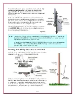
Install the
DXE SSVC-1PG
on the
ground rod approximately 9-1/2” from the
top of the ground rod as shown in
Figure
9
. Note the position of the
DXE-SSVC-
1PG
and the ground wire tab in as
compared to the
mounting plate of the active
Figure
9
antenna (Refer to the completed
assembly in
Figure 9
). Use the included
U-Bolt, flat washers, split
Figure 9
washers and hex nuts.
Figure 10 - three views
Mount the AVA-3 assembly to the ground rod as shown in
Figure 10
. Position
the assembly on the ground rod and adjust the height so the ground rod top is
not higher than the black insulated panel. This prevents unwanted interference
with the active element. Tighten the two U-Clamps to hold the assembly in
place.
Connect the second (longer) wire coming from the ground tab to the
AVA-3
antenna
GROUND
connection, use the wing nut and hand tighten only. The
forked terminal goes between the two washers on the
GROUND
terminal as
shown in Figure 10.
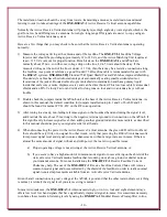
Installing the upper two Antenna Elements
The upper two elements are
installed to the antenna element
that is in place on the black
mounting plate. 3/8” element fits
inside the 1/2” element mounted
to the black mounting plate.
Use the #6 hardware and the
included Allen wrench to secure
this element in place.
Note: The
head of the socket head cap
screws will fit inside of the
larger hole and make contact
with the element that was
inserted.
Refer to
Figure 11
for
details. The overall length
assembled is 102”.
The upper 1/4” element fits inside the 3/8” element, Use the
Figure 11
#4 hardware and the included Allen wrench to secure the
upper element in place. Install the black vinyl cap in place
on the top element.


