3
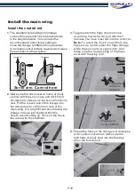
. Adjust the linkage in the control connector
to make sure the counterbalance leading
edge of the elevator and the rudder level
with the leading edge of the horizon stabilizer
and the vertical fin respectively.
Note:
Use a drop of thread lock on the screw
before secure the rod into place.
2.
neutral position, for computerized transmitters,
use the servo/channel sub-trim feature to make
each servo arm fully vertical.
Note
: Make sure the trims and the sub trims in
neutral position before making some mechanically
trim.
ake
sure all servo arms are as fully vertical with the
servo case as possible. If not, adjust the servo
arm by using the trim function on your radio.
Adjust the servo arms mechanically m
Make sure all the control surface trim in
4
. Adjust the control connector on the rear
landing gear steering arm to make sure
the wheel align with the centerline of the
fuselage.
5.
The motor should rotate counterclockwise
when viewing the plane from the front.
Or you will have to disconnect any two of
the motor plugs and plug them back to
each other’s socket.
Test the electric device
1.2
1.1
2
5
4
3.1
Rudder
Elevator
Elevator up/Stick Down
Elevator down/Stick up
Ruder left / Stick left
Rudder right / Stick right
P.9
Содержание SUPERMARINE SPITFIRE MK24 V2
Страница 1: ...INSTRUCTION MANUAL ...


