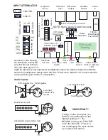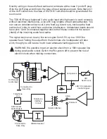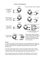
Pin Description
1
Remote LED/Start
2
0V
3
Remote AUTOmatic
4
Remote LED
5
Remote MANual
1
2
3
4
5
1
2
3
4
5
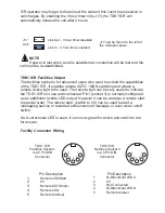
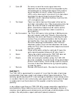
S/R operator may forget to disconnect the call and this could be expensive in
call charges. By enabling the 3 hour timer link (J17), the TDS1 S/R will
automatically release the call after 3 hours.
Link Out - 3 hour timer disabled
Link In - 3 hour timer enabled
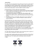
J17 can be found to the left of
the microprocessor.
J17
Link
NOTE
If power is lost when a call is established, connection will be lost and the
call must be re-established.
TDS1
Facilities Output
The facilities socket is for advanced users who want to extend the capabilities
of the TDS1 S/R. It enables remote AUTO / MAN switching and allows a
remote Active light to be used. The remote light can be very useful to indicate
the TDS1 S/R is in use and connected. Pin1 (socket 1) is normally configured
as an additional remote LED output. However it can be wired as a remote start
to special order. The remote start (switch to 0V) can be used to start a
messaging service or recorded announcement message or even as an on/off
switch.
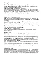
If a bi-directional LED is used, it can show green for Active and switch to red
for answer.
S/R
Pin Description
1
Bi-Directional LED A
2
0V
3
Not Connected
4
Bi-Directional LED B
5
Remote Answer
TDS1
Facilities Socket 1
is a 5 Pin DIN
Connector
S/R
TDS1
Facilities Socket 2
is a 5 Pin DIN
Connector
S/R
Facility Connector Wiring
Содержание TDS1 S/R
Страница 12: ...TDS1 S R Manual Iss1 cdr...


