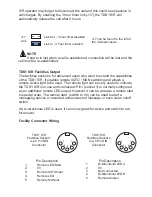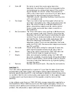
Close switch to
enable
AUTOmatic
mode
1
2
3
4
5
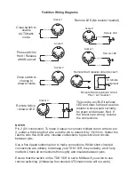
Facilities Wiring Diagrams
NOTES
Pin 2 (0V connection). To make it easier to connect multiple return wires to pin
2, solder a thick length of wire onto the pin to extend it by 10-15mm. Solder the
returns onto this thick wire. Insulate connections to prevent short circuits
between pins.
Use a fine tipped soldering iron to make connections. Whilst short circuited
connections are unlikely to damage your TDS1 S/R, they certainly won’t help
matters! Check all connections thoroughly and insulate between pins.
Ensure that the switch on the TDS1 S/R is set to MANual if you wish to use
remote switching. (Otherwise the remote AUTOmatic mode will not work).
Socket 1
Press switch to
Hold / Release
a MANual call
1
2
3
4
5
Socket 1
Remote LED (No resistor needed)
Socket 1
Remote LED
This can be any Bi-Directional
LED and does not need a series
resistor. Active would normally
be green and Answer, Red. If
the colours are wrong, reverse
the connections.
Remote Active
/ Answer LED
Socket 2
1
2
3
4
5
Close switch to
change to
Answer mode
Socket 2
1
2
3
4
5
1
2
3
4
5
0V
To remote
equipment
Remote Start equivalent circuit.
Pins 1 & 3 Socket 1
Remote Start (special order) Socket 1
1
2
3
4
5
Socket 1
Remote LED
1
2
3
4
5
Содержание TDS1 S/R
Страница 12: ...TDS1 S R Manual Iss1 cdr...


