background image

Page 7

60706-133

8290-01

MAINTENANCE

General Information

The main components of the generator are: armature, field
coils, cooling fan, brushes, brush holder assembly, end
brackets, rectifier and voltage regulator.  Before performing
any maintenance on the generator, isolate and/or disable the
drive system so the unit can not be accidentally started while
being repaired.

The troubleshooting chart lists various symptoms of poor
generator operation with possible causes and the appro-
priate corrective action. You will need a volt-ohm meter or
test light to check some of the causes. For some of the
other causes you will need to check generator speed. To
check generator speed you can use a frequency meter, a
tachometer, or a 120V-60Hz electric clock and a correctly
operating wrist watch. (Run the electric clock on generator
power and compare the clock’s second hand movement
with that of the wrist watch. They should run at the same
speed. If clock runs faster, generator speed is too high,
and vice versa.)

CAUTION: Equipment Damage
Most electrical equipment in North America operates
satisfactorily at frequencies between 58.5 and 62 Hz
(cycles per second.) Operating the generator at frequen-
cies outside that range may cause damage to the genera-
tor and/or to electrical equipment driven by the generator.

Periodical Maintenance

Service/maintenance items include periodic external physi-
cal inspection for missing hardware or damage to mounting
or drive system and checking the oil level in the gear case.
It is recommended that the generator be operated at least
monthly under normal loads to familiarize operators with the
procedures and controls as well as to dry out any accumu-
lated condensation or other moisture in the generator elec-
trical windings.  The maintenance and service attention
invested will insure getting the peak performance that was
designed into the unit.

Routine preventive maintenance minimizes costly repairs
and generator down-time. Before each use, inspect the
generator: gear case oil level should be correct, cooling
vents and screens should be clear, and generator mount-
ing hardware should be tight. Clean and inspect the
generator after storing it for long periods, and after using
it in extremely dusty conditions or in severe weather, such
as rain or blowing snow.

Lubrication

The generator bearings are factory lubricated and sealed,
and require no further lubrication.

The generator input shaft should be cleaned and lubricated
with a thin film of grease before installing the drive shaft and
each time it is removed.

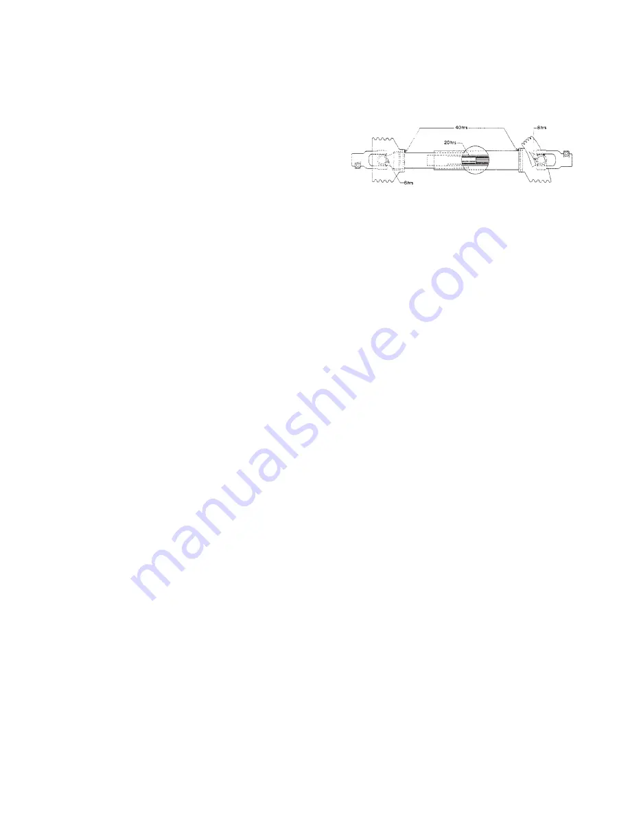
The drive shaft (tumbling bar) requires greasing. Keep the

universal joints in the coupling shaft free from grease and dirt
buildup.

NOTE:
Do not over lubricate the universal joints.

Check the generator gear case oil level before each use of
the generator. Maintain the oil level at oil level plug height.
(See page 6 for oil level plug location.) The generator is
shipped with lubricant in the gear case. Specifications for
gear case lubricant are:

API Service: GL-5
Grade: SAE 85W-9O-140
Amount: 2 pints

The following kinds of oil are recommended for use in the
generator gear case: Mobil SAE 85W90-140 API Service GL-
5, Sunoco/DX XL80W90-140 Kendal Three Star 85W-140,
Amoco 85W140 or equivalent.

CAUTION: Equipment Damage

Do not overfill generator gear case. Overfilling causes
overheating and oil seal failure.

Change the oil at least once every six months. Change it
more often if you use the generator in bad weather. Use the
following procedure to change generator gear case oil:

1.

Remove gear case breather. Soak breather in cleaning

solvent, then allow it to dry.

2.

Remove oil level check plug.

3.

Remove the oil drain plug, drain the oil into a clean oil

resistant container, 1 quart or larger. Check the oil for
metal. Fine metal dust in the oil does not indicate
trouble, but metal chips do. Dismantle the gear case and
look for damaged gears if you find metal chips in the oil.

4.

Replace the oil drain plug. Refill the gear case through

the breather port with new oil of the recommended type.
Fill the case up to oil level check plug height. (It will take
about 1 pint.)

5.

Replace the oil level check plug.

6.

Replace the breather

Cleaning and Inspection

Use a vacuum cleaner or dry low pressure compressed air
(regulated at 25-35 PSI) to clean the generator periodically.

WARNING
DO NOT CLEAN THE GENERATOR WHILE IT IS RUNNING.

Содержание 64864011

Страница 1: ...60706 133 12PTOC 3 25PTOC 3 Tractor Drive PTO Generators OWNERS MANUAL INSTALLATION AND OPERATION INSTRUCTIONS SAFETY FIRST READ THIS MANUAL BEFORE OPERATING YOUR GENERATOR ...

Страница 2: ...terial or workmanship under normal standby use average less than 50 hours per month and service For warranty service return the product within 36 months from the date of purchase transportation charges prepaid to your nearest factory authorized service station or the WINCO factory There is no other express warranty To the extent permitted by law any and all warranties including those of merchantab...

Страница 3: ...sible explosion and or fire a Keep a fire extinguisher nearby and know its proper use Fire extinguishers rated ABC by NFPA are appropriate 3 DEADLY EXHAUST GAS Exhaust fumes from any engine contain carbon monoxide an invisible odorless and deadly gas that must be mixed with fresh air a Operate only in well ventilated areas b Never operate indoors 4 NOISE HAZARD Excessive noise is not only tiring b...

Страница 4: ...isassembled in bag 5 Remove the four bolts which hold down the generator feet to the pallet 6 Lift the generator from the pallet by means of the lifting eye on the top of the generator 7 Inspect the generator carefully for freight loss or damage If loss or damage is noted at time of delivery require that the person making the delivery make note of the loss or damage on the freight bill or sign the...

Страница 5: ...ce The retainer pin will protrude approximately 3 8 when fully seated See Figure 1 7 Repeat steps 4 through 6 for each brass pin Make sure to connect the neutral lead cable identified and color coded in conformance with the applicable local electrical codes to the large diameter pin N on the plug WARNING Electrical Shock DURING THE NEXT STEP THE LOAD DISCONNECT PLUG SHOULD NOT BE PLUGGED INTO ITS ...

Страница 6: ...SONALINJURY IF THE GENERATOR IS TO BE USED AS A STANDBY POWER SOURCE A SPECIAL DISCONNECT SWITCH MUST BE INSTALLED TO SEPARATE THE GENERATOR AND THE COMMERCIAL POWER LINES THE DISCONNECT MUST ISOLATE THE GENERATOR FROM THE COMMERCIAL POWER LINES AND THE LOAD WHEN THE GENERATOR IS ON STANDBY AND MUST ISOLATE THE COMMERCIAL POWER LINES FROM THE LOAD AND THE GENERATOR WHEN THE GENERATOR IS SUPPLYING ...

Страница 7: ...motor not its starting current which is a lot higher Motor starting current requirements vary greatly by motor size and type Repulsion induction type motors are the easiest to start typically using 1 1 2 to 2 1 2 times as much current to start as to run capacitor type motors usually require 2 to 4 times as much current to start as to run split phase type motors are the hardest to start normally us...

Страница 8: ...HUTDOWNPROCEDURE 1 Switch off electrical load 2 Reduce speed of engine driving generator to idle 3 Disengage power take off drive and allow generator to coast to a stop WARNING Personal Injury Never try to manually stop the generator Always let it coast until it stops 5 Shut off the engine 4 Disconnect drive shaft tumbling bar power take off end first then generator end Figure 6 Figure 7 3 Make su...

Страница 9: ...nd generator mount ing hardware should be tight Clean and inspect the generator after storing it for long periods and after using it in extremely dusty conditions or in severe weather such as rain or blowing snow Lubrication The generator bearings are factory lubricated and sealed and require no further lubrication The generator input shaft should be cleaned and lubricated with a thin film of grea...

Страница 10: ...d of the armature are the generator output slip rings For proper generator output the surface of the slip rings must have a smooth shiny highly polished finish Normal brush seating will transfer a shiny black finish that will seat the copper surface This finish should not be removed unless it becomes dull or begins to build up Under sustained use it is advisable to check and if necessary polish th...

Страница 11: ...Either a high or low resistance reading will be obtained 7 Reverse the meter leads black lead to the DC NEG and red to the AC terminals each in turn An opposite reading should be observed 8 Check each terminal to the case An open circuit very high resistance reading should be observed A battery powered test light may be used Follow the same proce dures described above A good diode element will all...

Страница 12: ...ine if necessary 4 Incorrect field excitation 4 Check for worn brushes and weak or broken brush springs No load output low replace as required Check input AC voltage to rectifier Check rectifier output DC voltage to positive DC brush If no DC voltage is present at the brush replace the rectifier Check for dirty slip rings Clean them if they are dirty High voltage 1 Engine speed too fast 1 Check en...

Отзывы: