


Specification
057-230 ISSUE: 1
Page 22 of 100
2.13.4
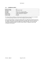
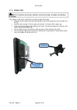
FIXING CLIPS
NOTE: In conditions of excessive vibration, mount the module on suitable anti-vibration
mountings.
The module is held into the panel fascia using the supplied fixing clips.
Withdraw the fixing clip screw (turn anticlockwise) until only the pointed end is protruding from
the clip.
Insert the three ‘prongs’ of the fixing clip into the slots in the side of the module case.
Pull the fixing clip backwards (towards the back of the module) ensuring all three prongs of the
clip are inside their allotted slots.
Turn the fixing clip screws clockwise until they make contact with the panel fascia.
Turn the screws a little more to secure the module into the panel fascia. Care should be taken
not to over tighten the fixing clip screws.
Fixing clip fitted
to module
Fixing clip
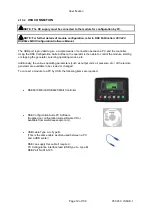
Содержание DSE6010 MKII
Страница 6: ...057 230 ISSUE 1 Page 6 of 100 11 1 WEEE WASTE ELECTRICAL AND ELECTRONIC EQUIPMENT 98...
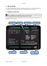
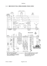
Страница 35: ...Installation Page 35 of 100 057 230 ISSUE 1 3 2 1 DSE6010 MKII TYPICAL WIRING DIAGRAM 3 PHASE 4 WIRE...
Страница 36: ...Installation 057 230 ISSUE 1 Page 36 of 100 3 2 2 DSE6020 MKII TYPICAL WIRING DIAGRAM 3 PHASE 4 WIRE...
Страница 37: ...Installation Page 37 of 100 057 230 ISSUE 1 3 3 ALTERNATE TOPOLOGY WIRING DIAGRAMS 3 3 1 GENERATOR...
Страница 38: ...Installation 057 230 ISSUE 1 Page 38 of 100 3 3 2 MAINS 6020 MKII ONLY...
Страница 99: ...This Page is Intentionally Left Blank...
Страница 100: ...This Page is Intentionally Left Blank...


