


Commissioning
Page 95 of 100
057-230 ISSUE: 1
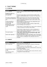
8.3 ALARMS
Symptom
Possible Remedy
Low oil Pressure fault
operates after engine has
fired
Check engine oil pressure. Check oil pressure switch/sensor and
wiring. Check configured polarity (if applicable) is correct (i.e.
Normally Open or Normally Closed) or that sensor is compatible with
the module and is correctly configured.
High engine temperature fault
operates after engine has
fired.
Check engine temperature. Check switch/sensor and wiring. Check
configured polarity (if applicable) is correct (i.e. Normally Open or
Normally Closed) or that sensor is compatible with the module.
Shutdown fault operates
Check relevant switch and wiring of fault indicated on LCD display.
Check configuration of input.
Electrical Trip fault operates
Check relevant switch and wiring of fault indicated on LCD display.
Check configuration of input.
Warning fault operates
Check relevant switch and wiring of fault indicated on LCD display.
Check configuration of input.
CAN ECU WARNING
CAN ECU SHUTDOWN
This indicates a fault condition detected by the engine ECU and
transmitted to the DSE controller.
CAN DATA FAIL
Indicates failure of the CAN data link to the engine ECU.
Check all wiring and termination resistors (if required).
Incorrect reading on Engine
gauges
Fail to stop alarm when
engine is at rest
Check engine is operating correctly. Check sensor and wiring paying
particular attention to the wiring to terminal 10 (refer to appendix).
Check that sensor is compatible with the module and that the module
configuration is suited to the sensor.
8.4 COMMUNICATIONS
Symptom
Possible Remedy
CAN DATA FAIL
Indicates failure of the CAN data link to the engine ECU.
Check all wiring and termination resistors (if required).
8.5 INSTRUMENTS
Symptom
Possible Remedy
Inaccurate generator
measurements on controller
display
Check that the CT primary, CT secondary and VT ratio settings are
correct for the application.
Check that the CTs are wired correctly with regards to the direction of
current flow (p1,p2 and s1,s2) and additionally ensure that CTs are
connected to the correct phase (errors occur if CT1 is connected to
phase 2).
Remember to consider the power factor (kW = kVA x powerfactor).
The controller is true RMS measuring so gives more accurate display
when compared with an ‘averaging’ meter such as an analogue panel
meter or some lower specified digital multimeters.
Accuracy of the controller is better than 1% of full scale. Generator
voltage full scale is 415 V ph-N, accuracy is ±4.15 V (1 % of 415 V ).
Содержание DSE6010 MKII
Страница 6: ...057 230 ISSUE 1 Page 6 of 100 11 1 WEEE WASTE ELECTRICAL AND ELECTRONIC EQUIPMENT 98...
Страница 35: ...Installation Page 35 of 100 057 230 ISSUE 1 3 2 1 DSE6010 MKII TYPICAL WIRING DIAGRAM 3 PHASE 4 WIRE...
Страница 36: ...Installation 057 230 ISSUE 1 Page 36 of 100 3 2 2 DSE6020 MKII TYPICAL WIRING DIAGRAM 3 PHASE 4 WIRE...
Страница 37: ...Installation Page 37 of 100 057 230 ISSUE 1 3 3 ALTERNATE TOPOLOGY WIRING DIAGRAMS 3 3 1 GENERATOR...
Страница 38: ...Installation 057 230 ISSUE 1 Page 38 of 100 3 3 2 MAINS 6020 MKII ONLY...
Страница 99: ...This Page is Intentionally Left Blank...
Страница 100: ...This Page is Intentionally Left Blank...


