background image

2

1.3 Technical 

Support and 
General 
Information

For technical support from DSC: Call toll free 1-800-387-3630 (Canada & US)

For general product information visit our web site: 

www.dsc.com

1.3.1 System Verification

The complete fire alarm system must be verified for proper installation and operation when:

the initial installation is ready for inspection by the Local Authority Having Jurisdiction;

any system component is added, changed or deleted;

any programming changes are made;

system wiring has been altered or repaired;

system failure due to external influences such as lightning, water damage or extended 
power outages has occurred.

1.3.2 Standby Power

The CFP-102/CFP-105 Fire Panel provides standby battery support for lead-acid rechargeable 
batteries. The required capacity of the standby batteries must be calculated using the charts 
and tables within the CFP-102/CFP-105 

Installation Manual

 for the period as required by 

national or local codes and standards. Even though the calculation table within the CFP-102/
CFP-105 

I

nstallation Manual

 includes a safety margin, lead-acid batteries commonly used for 

standby can have variable capacity as a result of age and ambient conditions. Periodic 
inspection for damage and the batteries’ ability to support the attached equipment is highly 
recommended.

firealarmresources.com

Содержание CFP-500

Страница 1: ...al contains information on limitations regarding product use and function and information on the limitations as to liability of the manufacturer The entire manual should be carefully read CFP 500 Dual Line Dialer Version 1 0 firealarmresources com ...

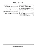
Страница 2: ...unication with the Fire Alarm Control Panel 5 3 3 Phone Line Communication 5 Section 4 Programming the CFP 500 6 4 1 How to program using the CFP 550 Handheld Programmer 6 4 2 DLS Programming 12 4 3 Panel Programming Section Descriptions 12 Section 5 Programming Worksheets 16 5 1 Dialer Programming Worksheets 16 5 2 Panel Programming Worksheets 21 Section 6 Warranty and Warning Information 22 6 1 ...

Страница 3: ...e rating 19 VDC to 27 5 VDC 1 2 Codes Standards and Installation Requirements 1 2 1 Relevant Codes and Standards The CFP 500 Dual Line Digital Dialer is designed to meet the DACT requirements of NFPA 72 1996 edition UL 864 Control Units for fire Protective Systems 1996 edition and in Canada CAN ULC S527 Standard for Control Units for Fire Alarm Systems 1999 edition 1 2 2 General Installation Requi...

Страница 4: ...s such as lightning water damage or extended power outages has occurred 1 3 2 Standby Power The CFP 102 CFP 105 Fire Panel provides standby battery support for lead acid rechargeable batteries The required capacity of the standby batteries must be calculated using the charts and tables within the CFP 102 CFP 105 Installation Manual for the period as required by national or local codes and standard...

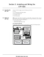
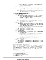
Страница 5: ...pacers 2 2 Wiring the CFP 500 NOTE Ensure that standby calculations are done before installing the dialer See the CFP 102 CFP 105 Fire Panel Installation Manual for all power information and calculation charts The current rating for the CFP 500 is 40 mA standby current 65 mA alarm current when dialing 2 2 1 Mount the CFP 500 The CFP 500 is located inside the main panel cabinet according to the fol...

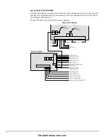
Страница 6: ...n of the Secur bus from the dialer to the main panel using the provided 4 pin polarized locking cable assembly Up to two telephone lines are connected to the Tip Ring T1 R1 terminals Connect the dialer according to the following diagram firealarmresources com ...

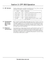
Страница 7: ... generated 3 3 Phone Line Communication The dedicated dialer is equipped with two phone line connections When an event occurs that initiates communications the first attempt at dialing will be on telephone line 1 If the attempt fails the dialer will then select telephone line 2 for the next attempt at dialing This will continue until the maximum number of dialing attempts is reached Please note th...

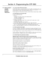
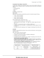
Страница 8: ...HEX digit A F press the key at any HEX data entry section The panel will enter the HEX programming mode The following indicates which number should be pressed to enter the corresponding HEX digit 1 A 2 B 3 C 4 D 5 E 6 F If another HEX digit is required press the key followed by the corresponding number entry After every HEX entry the programmer will return to standard number entry 4 1 4 Dialer Pro...

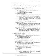
Страница 9: ...remaining attempts OFF If DTMF dialing is enabled in previous option 6 the dialer use DTMF dialing for all dialing attempts 8 Event Buffer Swinger Options ON Once an event reaches its swinger shutdown limit it will no longer log to the event buffer until the swinger shutdown is reset This avoids filling the Event Buffer with repeated events See Section 4 2 10 Swinger Shutdown for more information ...

Страница 10: ... The communicator will use the standard dialing procedure for every attempt 3 Pulse Dial Options ON Pulse Dialing Make Break Ratio is 33 67 OFF Pulse Dialing Make Break Ratio is 40 60 4 Handshake Options ON 1600 Hz Handshake The communicator responds to a 1600 Hz hand shake for bps formats OFF Standard Handshake The communicator responds to the handshake designated by the format selected 1400 or 2...

Страница 11: ...an event program the reporting code as 00 or FF Contact ID Contact ID is a specialized format that will communicate more information quickly using tones rather than pulses When using Contact ID obey the following Account numbers must be four digits The digit 0 is not used in this format substitute with HEX digit A All reporting codes must be two digits To prevent the panel from reporting an event ...

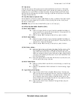
Страница 12: ...one num ber the panel will send the account number and reporting code followed by the key Hex C There is no ringback when using Pager format The panel has no way of confirming if the pager was called successfully a failure to communicate trouble will only be generated once the maxi mum number of attempts has been reached NOTE Do not use hexadecimal digit C in a reporting code when using Pager Form...

Страница 13: ...ry zone alarms restorals zone trouble alarms restorals maintenance troubles restorals Test Transmissions Sections 041 042 The dialer can be programmed to send test transmissions to the monitoring station to verify proper communications The Transmission Time of Day determines when the test transmission will occur The entry is four digits HH MM To disable the feature program the time as 9999 The Tes...

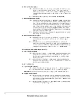
Страница 14: ...00 4 3 Panel Programming Section Descriptions With the addition of the dialer module the following additional items must be programmed in the control panel To program these sections use of the CFP 550 handheld programmer is required Follow the same procedure for programming as indicated in Programming using the CFP 550 on page 6 The control panel module address is 02 NOTE The installer code will n...

Страница 15: ... seconds On 0 5 seconds Off 0 5 seconds On 1 5 seconds Off repeat OFF NAC2 is Steady NAC2 will stay on steady for an alarm condition 3 NAC Silence Options ON Automatic Signal Silence is Enabled If enabled the timer starts on the first fire alarm and is restarted on subsequent fire alarms from other zones When the timer reaches 30 minutes from the last fire alarm the NAC s are restored to normal If...

Страница 16: ...Waterflow Zones cannot be Silenced Until physically restored the NAC s can t be silenced This applies to both manual and automatic sig nal silence However If the zone enters the trouble state open following the alarm short and alarm restore the zone shall be silenceable 4 3 3 Panel System Option Code Two 012 1 Auto Verify Fault Options ON Auto Verify Fault is Alarm If a zone initiates an auto veri...

Страница 17: ...ction the 20 event buffer memory can be viewed Upon entry the event number will be displayed along with the time and date stamp of when that event occurred Pressing the key will display the event description Pressing again will toggle back to the event number with date and time stamp Pressing the key or the key will scroll through the event buffer with event 001 being the first and event 20 being ...

Страница 18: ...unicator Call Directions 033 Zone Trouble Restore Communicator Call Directions Default 2600 01 10 bps 1400 Hz handshake 05 Contact I D 02 10 bps 2300 Hz handshake 06 SIA 03 20 bps 1400 Hz handshake 07 Pager 04 20 bps 2300 Hz handshake Default 06 1st Phone Number 06 2nd Phone Number Default Option ON Option OFF OFF Options 1 6 Future Use OFF Option 7 Telephone Number 2 Disabled ON Option 8 Telephon...

Страница 19: ...se MUST be enabled ON Option 3 Future use MUST be enabled OFF Option 4 3rd Phone Number Enabled 3rd Phone Number Disabled OFF Option 5 Alternate Dial 1st 3rd Call 1st Number Backup to 3rd OFF Option 6 Pulse Dialing DTMF Dialing OFF Option 7 Switch to Pulse Dialing On 4th Attempt DTMF Dial For All Attempts ON Option 8 Event Buffer Follows Swinger Shutdown Event Buffer Always Logs Events Default Opt...

Страница 20: ...tion 5 ID Tone Enabled ID Tone Disabled OFF Option 6 2100 Hz ID Tone 1300 Hz ID Tone OFF Option 7 Future use OFF Option 8 Future use Default 000 Zone Alarm Restore Valid Entries are 000 255 000 Zone Supervisory Restore 000 Zone Trouble Restore 000 Maintenance Trouble Restore Default 003 Number of valid checks required 001 255 x 10 seconds Default 000 Valid entries are 000 255 hours Default 007 Val...

Страница 21: ...Zone 2 Trouble Zone 5 Trouble Zone 3 Trouble Zone 1 Trouble Restoral Zone 4 Trouble Restoral Zone 2 Trouble Restoral Zone 5 Trouble Restoral Zone 3 Trouble Restoral AC Failure Trouble Alarm General System Trouble Battery Trouble Alarm General System Supervisory Ground Fault Trouble Alarm Secur bus Trouble NAC Trouble Alarm AC Failure Trouble Restoral General System Trouble Restore Battery Trouble ...

Страница 22: ...umber 32 digits 421 DLS Access Code 4 digits 422 DLS Downloading ID Code 4 digits 902 Dialer Event Buffer Viewing 999 Dialer Default Default 012 Valid entries are 000 255 rings Default 060 Valid entries are 000 255 seconds Default 000 Valid entries are 000 254 seconds Default 2600 Default 2600 firealarmresources com ...

Страница 23: ... Option 3 30 min Automatic Signal Silence Enabled Automatic Signal Silence Disabled OFF Option 4 NAC2 is Strobe NAC2 is Standard Bell OFF Option 5 60 sec Signal Silence Inhibit Enabled Signal Silence Inhibit Disabled ON Option 6 Walk Test is Audible Walk Test is Silent OFF Option 7 60 sec Waterflow Zone Delay Enabled Waterflow Zone Delay Disabled ON Option 8 Active Waterflow Zones can be Silenced ...

Страница 24: ...ife is a function of the device environment usage and type Ambient conditions such as high humidity high or low temperatures or large temperature fluctua tions may reduce the expected battery life While each transmitting device has a low battery monitor which identifies when the batteries need to be replaced this monitor may fail to operate as expected Regular testing and maintenance will keep the...

Страница 25: ...otect the occupants or their belongings Component Failure Although every effort has been made to make this system as reliable as possible the system may fail to function as intended due to the failure of a component Inadequate Testing Most problems that would prevent an alarm system from operating as intended can be discovered by regular testing and maintenance The complete system should be tested...

Страница 26: ... for failure to repair the product under this warranty after a reasonable number of attempts will be limited to a replacement of the product as the exclusive remedy for breach of warranty Under no circumstances shall Digital Security Controls Ltd be liable for any special incidental or consequential damages based upon breach of warranty breach of contract negligence strict liability or any other l...

Страница 27: ...ne Trouble Rest zone exhibits a trouble condition zone trouble condition has been restored T R 3 73 See Table 3 265 266 AC Fail Trouble Rest AC power to control panel is disconnected or inter rupted AC power restored both codes follow the AC Trouble Delay MA R 3 A1 AT 00 AR 00 265 266 Battery Trouble Rest control panel battery is low battery restored MA R 3 A2 YT 00 YR 00 265 266 Ground Fault Trou...

Страница 28: ... 1 13 Water Flow 1 4A General Alarm 1 57 Low Bottled Gas Level 1 14 Heat 1 4A General Alarm 1 58 High Temp 1 15 Pull Station 1 43 Expansion module failure 1 59 Low Temp 1 16 Duct 1 44 Sensor tamper 1 61 Loss of Air Flow 1 17 Flame 1 45 Module Tamper Zone Definition Alarm Rest Rep Codes Trouble Rest Rep Codes Zone Definition SIA Auto Rep Codes Trouble Rest Rep Codes 00 Null Zone No transm No transm...

Страница 29: ...6500 Bell Mobility Pager 10 bps 1400Hz handshake Yes Yes Yes Yes Yes Yes Yes 10 bps 2300Hz handshake Yes Yes Yes Yes Yes Yes Yes 20 bps 1400Hz handshake Yes Yes Yes Yes Yes Yes Yes 20 bps 2300Hz handshake Yes Yes Yes Yes Yes Yes Yes SIA level 2 Yes Yes Yes Yes Yes Contact ID Yes Yes Yes Yes Yes Pager N A N A N A N A N A N A N A Yes Version V1 00 V1 83 V1 2 2 20 96 SIA 9004I 960626 Rev4 4d D6500 L ...

Страница 30: ...rovided jacks or equivalent in such a manner as to allow for easy immediate disconnection of the terminal equipment Standard jacks shall be so arranged that if the plug connected thereto is withdrawn no interference to the operation of the equipment at the customer s premises which remains connected to the telephone network shall occur by reason of such withdrawal INCIDENCE OF HARM Should terminal...

Страница 31: ...firealarmresources com ...

Страница 32: ... 2001 Digital Security Controls Ltd Toronto Canada Tech Line Canada US 1 800 387 3630 www dsc com Printed in Canada 29005860 R002 firealarmresources com ...
Отзывы: