– 13 –
8.3 TIG WELDING
− Prepare the joint(s) to be welded. Select the
electrode suitable for the application and insert it into
the electrode holder as described in the
manufacturers literature.
− The tungsten should extend 3-6mm past the end of
shroud but no greater than the gas shroud diameter.
− With the earth clamp, electrode holder and gas bottle
connected, connect the machine to the power supply.
The power indicator (11) will illuminate as
confirmation. Set the amperage adjustment
appropriate to the selected electrode size.
− Secure the earth clamp to a clean sound section of
the parent metal in the vicinity to the intended weld.
With all safety equipment in place and personal
protective clothing on begin welding.
Note: Ensure the gas bottle regulator is open.
− Open the torch gas control valve.
− Lower the electrode down toward the parent metal.
When near the ‘hot start’ feature will aid start up of
the initial arc.
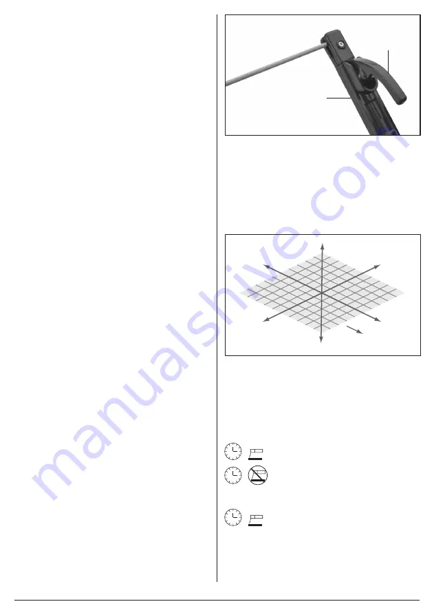
8.4 MMA/ARC WELDING – FIG.11
− Prepare the joint(s) to be welded.
− Insert the electrode suitable for the application into
the electrode holder
(6)
while pressing lever
(6.1)
.
− With the earth clamp and electrode holder
connected, connect the machine to the power supply.
The power display will illuminate as confirmation. Set
the amperage appropriate to the selected electrode
size.
− Secure the earth clamp to a clean sound section of
the parent metal in the vicinity to the intended weld.
− With all safety equipment in place and personal
protective clothing on begin welding.
− Lower the electrode down toward the parent metal
and strike the arc.
− The position of the electrode is critical to the arc and
the end result.
− Achieving a good weld will take practice. For more
detailed information refer to a industry standard
welding publication and/or seek training on the
subject.
− Use of an anti-spatter spray – Draper stock
No.05709 – will help to achieve a cleaner finished
weld.
11
FIG.
(6)
(6.1)
8.5 DIRECTION OF WELD – FIG.12
− Strike the initial arc perpendicular to the parent metal
before moving the electrode holder in the direction of
travel 20-30° (Z,Y axis) and tilt it 20-30° (Z,X axis).
− Maintain a constant gap between the electrode tip
and the weld pool of approximately 1 – 1.5 × the
diameter of the electrode for a stable arc.
Z
-Z
-X
-Y
XY
Direction
of weld
12
FIG.
8.6 DUTY CYCLE
Duty Cycle is a percentage of 10 mins, in which a
machine can operate at a rated load without overheating
and interruption from the thermal cut-out device.
Example:
150A @ 30% Duty factor:
150A welding for 3 minutes
7 minutes down time
Example:
95A @ 100% Duty factor:
95A continuous welding
To increase the operation time, reduce the amperage.
Note: The heating tests have been carried out at
ambient temperature and the duty cycle (duty factor) at
20°C has been determined by simulation.
Содержание Expert 70052
Страница 18: ......


