background image

– 14 –

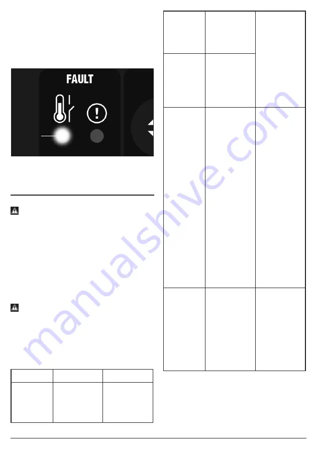
8.7  THERMAL CUT-OUT – FIG.13

If welding for extended periods, the thermal cut-out will 

activate and the LED indicator 

(M) 

will illuminate, 

prohibiting use of the machine until sufficiently cool.
Caution! After completion of any welding task, leave the 

unit connected to the power supply for a sufficient period 

to allow the cooling fan to continue working.

13

FIG.

9.  MAINTENANCE AND 

TROUBLESHOOTING 

9.1 MAINTENANCE

 Warning!

If the welding machine has just been turned off, you 

must not conduct any internal checks or 

maintenance for at least 5 minutes after the power 

distribution box switch or power switch is 

disconnected so that the capacitor inside the 

welding machine is completely discharged. 


− It is crucial to carry out regular checks on this product 

to ensure optimum performance and safe operation.


− The inspection table below offers guidance for the 

checking of components for general wear and tear or 

damage. Wherever necessary, clean or replace such 

items.

 Warning! Any live electrical parts touched may 

cause fatal electric shock or serious burns.
For your own safety, turn the switch off and remove the 

plug from the power  supply socket when carrying out 

any form of maintenance or cleaning. If in doubt, consult 

Draper Tools, or an authorised service agent.

Welding power supply:

Component

Check points

Advisories

Front panel


− Check if any 

components 

are 

damaged or 

loose.

Tighten or 

replace where 

necessary

Front panel


− Check if the 

lower quick 

socket is 

loose.

The lower quick 

socket is a 

regular item. If a 

defect occurs, it 

will be 

necessary to 

check the 

inside, re-fasten 

or replace 

components 

where 

necessary.

Rear panel


− Check if the 

air intake of 

the cooling 

fan has 

foreign 

objects 

sticking to it.

Routine


− Power on, 

and then 

check if the 

appearance 

has fading or 

too hot 

traces.


− Check if the 

cooling fan 

has stable 

operation 

sound.


− Check if the 

cooling fan 

takes in air 

from the air 

intake, if 

odour, 

abnormal 

vibration or 

noise 

(especially 

during 

welding) 

occurs.

In-case of 

defects, it is 

necessary to 

check the inside 

of the device.

Top plate, 

bottom 

plate and 

side panel


− When the 

machine 

cover is 

installed 

onto the 

housing, 

check if it is 

loose.


− Check if 

bolts are 

loose.

In case of 

defects, it is 

necessary to 

replace or 

fasten 

components, 

etc., as 

required.

(M)

Содержание Expert 70052

Страница 1: ...ch the product has been designed and contains all the necessary information to ensure its correct and safe use By following all the general safety instructions contained in this manual it will ensure both product and operator safety together with longer life of the product itself All photographs and drawings in this manual are supplied by Draper Tools to help illustrate the operation of the produc...

Страница 2: ...death Caution Information that draws attention to the risk of damage to the product or surroundings 1 3 EXPLANATION OF SYMBOLS Warning Read the instruction manual Warning Wear suitable welding eye face protection Warning Wear ear defenders During grinding operations Warning Wear protective gloves Keep out of the reach of children Warning Danger of electric shock Danger of fire Danger of explosion ...

Страница 3: ...unattended and remove the plug from the socket when not in use Do not use welding cables unsuitable for the amperage Ensure the earth clamp is adjacent to the weld seam secured to bare metal and when not in use is insulated for safety Keep all equipment well maintained The operator shall prevent gas cylinders in the vicinity of the workpiece from becoming part of the welding circuit Fumes Gases ca...

Страница 4: ... eyes and impair vision infra red heat radiation can damage skin and eyes Such radiation can be direct or reflected from surfaces such as bright metals and light coloured objects Gas cylinders Gas cylinders should be located or secured so that they cannot be knocked over Shield gas containers can explode if damaged Take care when handling Ensure gas cylinders are shut off when not in use and betwe...

Страница 5: ...e product The packaging material should be retained during the warranty period in case the product needs to be returned for repair Warning Some of the packaging materials may be harmful to children Do not leave any of these materials in reach of children If any of the packaging is to be thrown away make sure they are disposed of correctly according to local regulations 5 TECHNICAL DESCRIPTION 5 1 ...

Страница 6: ...clear Equally ensure no debris can be drawn into the machine 6 3 CONNECTION TO THE POWER SUPPLY Make sure the power supply information on the product s rating plate is compatible with the power supply you intend to connect it to A suitable plug must be fitted by a qualified electrician This product s wiring has insulation stripped in preparation for wiring a 32A plug not supplied It is designed fo...

Страница 7: ...ver as a general rule for DC output negative electrode machines a 1 6mm thorium oxide tungsten electrode will suffice Tungsten Ø Amp Range 1 2mm 70A 1 6mm 70 140A 2 4mm 140 250A 3 2mm 240A The selection of the ceramic shroud is based on the tungsten electrode and should be 4 to 6 times the tungstens diameter For example a 1 6mm tungsten could be used with a No 4 6 4mm ceramic shroud a No 5 8 0mm o...

Страница 8: ... hose to the TIG torch To attach the TIG torch 7 to the front panel coupling marked GAS 4 plug in and twist to lock Attach the earth clamp 8 into the coupling marked 5 plug in and twist to lock To connect the torch trigger cable 7 1 fit the 2 pin plug into the corresponding connection port marked 2 Secure the outer ring by screwing it onto the threaded outside part of the trigger connection port C...

Страница 9: ...pedal controls the level of current incrementally until the maximum level set by the dial is reached 7 FIG 7 4 MMA MANUAL METAL ARC SETUP FIG 8 To attach the electrode holder 9 to the front panel insert the plug into the connection port marked 1 and twist to lock Attach the earth clamp 8 into the connection port marked 5 plug in and twist to lock 8 FIG 7 5 MMA ARC WELDING FILLER ROD ELECTRODE SELE...

Страница 10: ...and the consumable electrode rod melts the parent metal and the filler metal in a weld pool The electrode s flux coating reacts during this process and develops into a shield gas protecting the weld bead Part of this reaction leaves a trail of slag which solidifies behind the weld pool protecting the weld as it cools The most common varieties of electrodes are cellulosic rutile and basic the latte...

Страница 11: ...ndicating light no load voltage indicator light M Alarm light Welding machine overheat over current alarm light 7 7 FUNCTION PARAMETERS Function Description Adjust Range Default value Pre flow The time of gas prior to welding 0 10 S 0 1 S Hot start Hot start current 5 200A 100A Arc start current The preset starting current is adjusted when arc closing is controlled 5 200A 40 A Slope up When arc cl...

Страница 12: ...om the workpiece to the tungsten needle to the negative current current flowing from the tungsten needle to the workpiece in other words to act in one cycle If the positive current decreases increases at a given time the negative current increases decreases accordingly The positive current is mainly used for welding while the negative current is mainly used for cleaning the oxide film of the workp...

Страница 13: ...ctrode size Secure the earth clamp to a clean sound section of the parent metal in the vicinity to the intended weld With all safety equipment in place and personal protective clothing on begin welding Lower the electrode down toward the parent metal and strike the arc The position of the electrode is critical to the arc and the end result Achieving a good weld will take practice For more detailed...

Страница 14: ...c shock or serious burns For your own safety turn the switch off and remove the plug from the power supply socket when carrying out any form of maintenance or cleaning If in doubt consult Draper Tools or an authorised service agent Welding power supply Component Check points Advisories Front panel Check if any components are damaged or loose Tighten or replace where necessary Front panel Check if ...

Страница 15: ...metal position with your hand etc In order to maintain the performance of this product over time regular checking is advised Inspect and clean the housing interior Remove any dirt dust or foreign matters Use compressed air without water dry air to blow accumulated detritus away Regular checking intervals should generally be conducted every 6 months However this should be extended to every 3 months...

Страница 16: ...unplug the power supply plug of the HF arc striking power supply If the fault indicator is still on it will indicate that some field effect tubes on the MOS plate are broken Find and replace them with ones of the same type If the fault indicator is off it will indicate that the voltage rise transformer in the HF arc striking circuit on the power supply plate is broken Replace The previous steps ha...

Страница 17: ...isuse careless or unsafe handling alterations accidents or repairs attempted or made by any personnel other than the authorised Draper warranty repair agent Note If the tool is found not to be within the terms of warranty repairs and carriage charges will be quoted and made accordingly This warranty applies in lieu of any other warranty expressed or implied and variations of its terms are not auth...

Страница 18: ......

Отзывы: