background image

28

TITRE

TITRE

TITRE

INSTALLING THE PIPING SYSTEM 

INSTALLING THE PIPING SYSTEM 

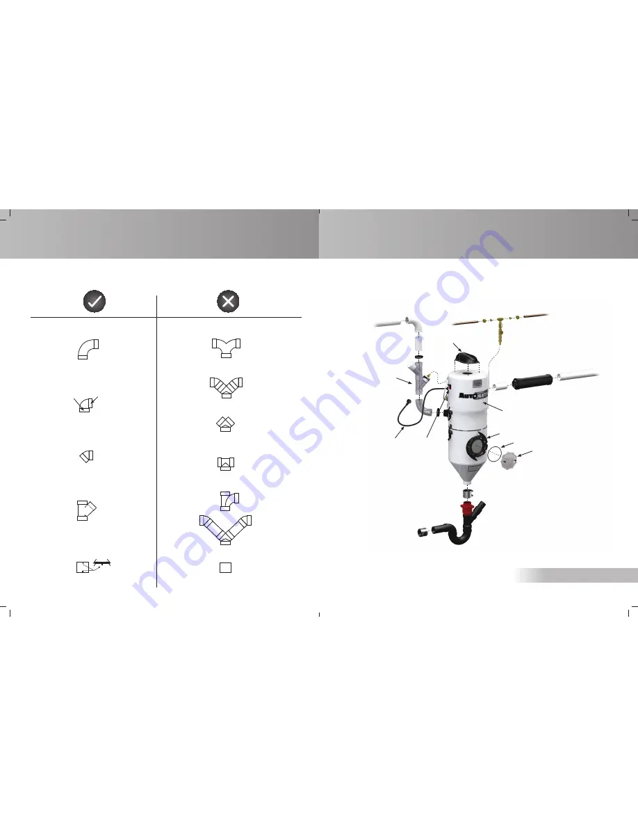
EXAMPLES OF PROPER AND IMPROPER INSTALLATIONS

Joint with inside stoppers

Thick wall

Thin wall  

For wall plates only

Smooth joint without inside stoppers

9

TITRE

TITRE

TITRE

UNIT DESCRIPTION

UNIT DESCRIPTION

DV1A150 / DF1A150

Vacuum pipe

Audioprotek

muffler

24V plug

Cold water sup

ply

One motor unit

Porthole

O-ring

Porthole window

To outside v

ent

Dust entry

Water d

ischarge

(Dia: 2in / 5c

m)

Power cord

Содержание Automatik Series

Страница 1: ...PRINTED IN CANADA 07 11 OWNER S MANUAL For an online version of this manual readable with a smart phone AUTOMATIK SERIES ...

Страница 2: ...4 PM eastern standard time UTC 5 T 1 800 408 1448 450 467 1448 F 1 877 408 2225 450 467 2225 info drainvac com www drainvac com 150 Brunet street Mont St Hilaire Qc J3G 4S6 Canada www youtube com drainvacchannel www facebook com drainvac SOLUTION 1 Check the circuit breaker in your electrical panel 2 Check the unit s circuit fuse breaker 3 Check the 24 volt circuit as follows Try to establish elec...

Страница 3: ...The symbol representing a garbage bin on wheels on the unit s label Figure C attests to this requirement You must ensure that at the end of its life cycle your unit is reclaimed treated and recycled by an authorized firm For more information contact your municipal waste management department MOTOR BRUSHES WEEE GUIDELINES Figure C 3 TITRE TITRE TITRE TABLE OF CONTENTS TABLE OF CONTENTS HOW THE SYST...

Страница 4: ...nit To proceed you just have to remove the porthole glass as illustrated by pivoting it in an anti clockwise motion using the handles Your Automatik system is very user friendly and we recommend a visual inspection through the porthole once a year or when needed If you wish to clean the inside of the unit refer to the following section Regular Maintenance Use a scouring sponge to especially clean ...

Страница 5: ... DVDC40 15 amp circuit 120v DFDC40 16 amp circuit 240v 24 volt wires supplied with the unit Electrical Panel If you experience voltage surge problems on your electrical circuit in spite of adequate connections a high magnetic circuit breaker can be installed on your electrical panel Contact an electrician for more information 5 TITRE TITRE TITRE HOW THE SYSTEM WORKS HOW THE SYSTEM WORKS The water ...

Страница 6: ... cm 12 dia x37 30cmdia x93cm 15 dia x49 38cmdia x122 5cm 15 dia x49 38cmdia x122 5cm 15 dia x49 38cmdia x122 5cm 15 dia x49 38cmdia x122 5cm 12 dia x37 30cmdia x93cm 15 dia x49 38cmdia x122 5cm 15 dia x49 38cmdia x122 5cm 15 dia x49 38cmdia x122 5cm 15 dia x49 38cmdia x122 5cm Technical label 31 TITRE TITRE TITRE ELECTRICAL POWER SUPPLY ELECTRICAL POWER SUPPLY All the central vacuum system models ...

Страница 7: ...LS 75 78 75 78 MOTOR MOTOR 1 2 in series 1 2 in series AMPS AMPS 13 18 7 5 11 DIMENSIONS in cm FOR MODELS FOR MODELS DIMENSIONS in cm 15 dia x12 38cmdia x30cm 15 dia x12 38cmdia x30cm 15 dia x12 38cmdia x30cm 15 dia x12 38cmdia x30cm Booster heads are also available on certain models to add extra power to your unit If your Automatik system is equipped with an auxiliary 24V outlet you can add one o...

Страница 8: ...e is available Please note that a standard tank system can be replaced by a lower tank system at any time and on all models Contact your retailer or your distributor for more information Please note that the default models illustrated in this manual will be the standard tank model to simplify the illustrations Standard Tank Lower Tank ADVANTAGES OF A LOWER TANK 29 TITRE TITRE TITRE INSTALLING THE ...

Страница 9: ... inside stoppers Thick wall Thin wall For wall plates only Smooth joint without inside stoppers 9 TITRE TITRE TITRE UNIT DESCRIPTION UNIT DESCRIPTION DV1A150 DF1A150 Vacuum pipe Audioprotek muffler 24V plug Cold water supply One motor unit Porthole O ring Porthole window To outside vent Dust entry Water discharge Dia 2in 5cm Power cord ...
Страница 10: ...ent Dust entry Rubber hand Power cord Water discharge Dia 2in 5cm 27 TITRE TITRE TITRE INSTALLING THE PIPING SYSTEM INSTALLING THE PIPING SYSTEM DIAGRAM OF A COMMERCIAL INSTALLATION In the basement connected under a pipeline under the floor Back to back Always have a slight inclination of the piping towards the unit Under the floor Through the ceiling Installation example in series Inclination Inc...
Страница 11: ...connected above a pipeline under the floor On an intermediary floor Always have a slight inclina tion of the piping towards the unit Inclination 11 TITRE TITRE TITRE UNIT DESCRIPTION UNIT DESCRIPTION DV2A31 DF2A31 Vacuum pipe Audioprotek muffler 24V plug Cold water supply 2 motor unit Porthole O ring Porthole window To outside vent Dust entry Rubber hand Power cord Audioprotek muffler Water discha...

Страница 12: ...e where to locate the wall inlets use the length of the vacuum hose as a basis measuring the furthest point from the wall where the wall inlets are to be installed Do the same for all the wall inlets until all areas of the house or building can be reached with the vacuum hose by moving it from one wall inlet to another don t forget to install one in the garage or outside to vacuum your car If your...

Страница 13: ...ll models equipped with only one motor include only one muffler centered on the top of the unit 13 TITRE TITRE TITRE UNIT DESCRIPTION UNIT DESCRIPTION DVDC40 DFDC40 SERIES CONFIGURATION FOR OPTIMUM SUCTION POWER Vacuum pipe Audioprotek muffler 24V plug One motor booster head 24V plug Cold water supply One motor unit Porthole O ring Porthole window To outside vent Dust entry Power cord Audioprotek ...

Страница 14: ...low Suction Power 120 H2O 2832 mmH2O Air Flow 200 CFM 340 m3 h Water discharge Dia 3in 7 6cm 23 TITRE TITRE TITRE INSTALLING THE UNIT INSTALLING THE UNIT STEP SEQUENCE STEP SEQUENCE Steel Muffler STEEL MUFFLER MODELS DV1A150 AND DF1A150 Some units are equipped with a red steel muffler to absorb the noise produced by more powerful systems Contrary to plastic mufflers this steel muffler must be inst...

Страница 15: ... to adjust the time lapse during which the unit will deactivate before restarting its cycle the default time lapse is 20 seconds With a lower tank model the unit can reactivate as soon as there is no wastewater left to flow through the rubber hand in other words when all the wastewater is in the lower tank If the unit s drain is located very close to the pipe leading to the sewer and that there is...

Страница 16: ...er for the clamps supplied with the unit THE TOOLS YOU WILL NEED or 21 TITRE TITRE TITRE INSTALLING THE UNIT INSTALLING THE UNIT STEP SEQUENCE STEP SEQUENCE Some units are equipped with two water injectors In this case it is important that they be positioned facing each other so that the water covers a greater surface POSITIONING THE WATER INJECTORS ON THE DUST INLET Connect the unit s water outle...

Страница 17: ...NG THE UNIT INSTALLING THE UNIT FIRST THINGS FIRST FIRST THINGS FIRST We recommend installing the system on the lowest level of the building to avoid having to work against gravity The basement is generally the most ideal location near the building s main drainpipe A cold wa ter pipe must also be available and connected to the unit If there is no basement the garage or a storage room will do It is...

Страница 18: ...5 cm Installation with lower tank Tank 40 100 cm Unit 65 165 cm 19 TITRE TITRE TITRE INSTALLING THE UNIT INSTALLING THE UNIT STEP SEQUENCE STEP SEQUENCE Lift the unit and slide its support onto the wall bracket If your unit is equipped with a lower tank repeat the same steps to attach it to the wall If your unit is equipped with one or several booster heads repeat the same steps to attach it or th...

Отзывы: