background image

35

Cause:

  The starting Y position of the cut is a negative value (you can see coordinates 

on plotter’s display when you move the media with arrows). 

Keep in mind also the 

offset  influences  the  starting  position  of  the  cut.  So,  if  you  start  the  cut  at  Y 

coordinates 0, while you have an offset Y value of -10, you will still get this error.


This error might happens when the media has been just loaded.

Fix: 

 Move to the next black-mark. If it is not enough, forward until you  have reached Y 

coordinate value major than 0.

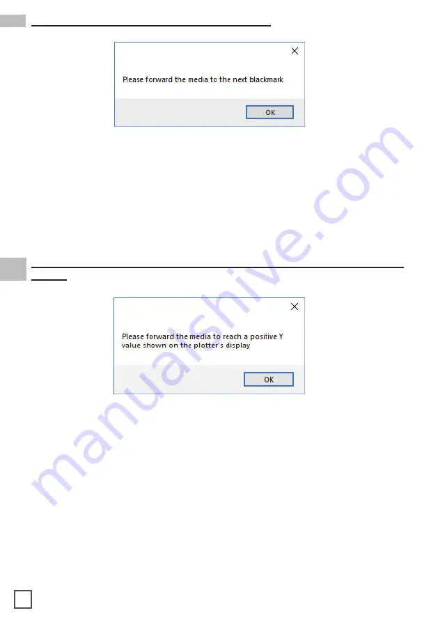
Please forward the media to the next black-mark

Cause:

  The starting Y position of the cut is a negative value (you can see coordinates on 

plotter’s display when you move the media with arrows).

This error might happens when the media has been just loaded.

Fix:  

Move forward until you have reached positive Y coordinates.

Please forward the media to reach a positive Y value shown on the plotter’s 

display

Содержание SCR22

Страница 1: ...USER MANUAL SCR22 SCR22PL SCR35 SCR35PL Digital label finishing system this product is certified WITH GRAPHTEC CE7000 40 REV 02...

Страница 2: ......

Страница 3: ...e you need to return the material If we receive the system in non original packaging the warranty will be void IMPORTANT The latest version of the Scorpio Series software is available on our websites...

Страница 4: ......

Страница 5: ...a job How load the matrix remover slitter How to load the matrix remover core holder How to load the rewinder core holder and set the slitter module How to add or remove blade holder Metal guide alig...

Страница 6: ...s behind the on off panel 3 Using a screwdriver install the outer disc on the Core Holder for printed rolls SYSTEM REQUIREMENTS HOW TO INSTALL OUTER DISC HOW TO INSTALL THE PLOTTER dongle usb Camera u...

Страница 7: ...y step instructions to complete the installation Please DO NOT connect the scorpio USB to your pc before the installation is complete 2 Click NEXT 4 Click NEXT 5 Click YES 6 In process HOW TO INSTALL...

Страница 8: ...12 Choose the right model name of your Graphtec CE7000 40 Click NEXT 13 Wait until the sign Update for the Graphtec CE7000 40 driver was completed shows up You may need to restart the computer Click...

Страница 9: ...Windows start menu If the USB dongle is not installed correctly or is unplugged the following error will appear The grey handle must match with the grey holder and the black handle with the black hold...

Страница 10: ...h end At this point you can tighten the core holder When the LEDs on the control board are off the device works on a manual feeding Move the media through the rollers and press the FORWARD button The...

Страница 11: ...sible air bubbles When the green LED is on the automatic feeding is activated and operated by the ultrasonic sensor When both yellow and green LEDs are on it indicates the system is in error mode The...

Страница 12: ...amaged or if the tension is too loose the media will not be laminated properly Pull the laminated media underneath the tension arm than pass it through the aluminium rollers the guide can be adjusted...

Страница 13: ...ure the distance in MM between the top of one black mark to top of the next black mark key in this value in the DISTANCE BETWEEN BLACKMARKS box section HOW TO RUN THE CUT TEST AND START A JOB IMPORTAN...

Страница 14: ...ess OPEN PDF or OPEN LAST JOB to load the cut file 2 Set the copy mode ON and set 2 as number of copies 3 Click START 4 Check the horizontal position and the gap between the cuts 5 If necessary adjust...

Страница 15: ...ng then through the clutch system Close the loading system and the media will be automatically loaded into the clutch path The user can adjust the clutch force thanks to the position of the clutch sys...

Страница 16: ...Cardboard core s width should equal or narrower the width of the finished roll 2 Pull the media through the aluminium rollers and attach the labels to the core using a waste label WARNING Before start...

Страница 17: ...r of the labels tighten the thumb screw once the blade is in position Lower position C the blade cut the media OPEN CLOSE B C A The black knobs lock the slitter module in the requested position Screw...

Страница 18: ...into the waste basket under the hole Press RESUME to start your finishing process Remove the iron bar by unscrewing the black thumb screw 1 Slide in or out the blade holder Relocate the slide iron ba...

Страница 19: ...y on the popup window Ensure the media is loaded properly Raise the lever on the plotter then press the number 2 on control panel wait until the display will show READY as the status Then press retry...

Страница 20: ...m distance betwen black mark and label graphics on bottom side Black mark MUST be the leftmost object for round or complex labels black mark can partially overlap the left side of label 17 BLACK MARK...

Страница 21: ...3 Click Start HOW TO CUT BLANK LABELS WARNING Please note that enabling the blank label feature will disable both cut test and Y offset adjustment The diecut shape must be attached to the bottom edge...

Страница 22: ...TWARE 3 When the display shows DEFAULT SETTING press button 1 4 Press button 1 HOW TO RESTORE PLOTTER SETTINGS 1 Turn off the plotter 2 Turn on the plotter while keeping pushed the UP arrow on the pan...

Страница 23: ...then enter 10 Press button 2 11 Wait until on the display appears READY 12 Press PAUSE MENU then go to I F press up arrow key 13 Go to Command press 2 14 Select GPGL press 1 then enter 16 Restart plot...

Страница 24: ...ed can be set within the range of 50 to 600 WHEN AND HOW TO REDUCE THE PLOTTER FEEDING SPEED 17 Wait until on the display appears READY 21 18 Open the Cutting manager and click on Advanced and then se...

Страница 25: ...sion arm idle at the desired position using a paper clip keep pushed the button into the small hole until the yellow led will flash and the unit will emit an acoustic signal 3 The ultrasonic sensor ha...

Страница 26: ...LAMINATION MATRIX REMOVER SLITTER MODULES SPEED ROTATION LAMINATION MODULE SCR22PL AND SCR35PL MODELS MATRIX REMOVER SLITTER MODULE ULTRASONIC TENSION CONTROLLER ULTRASONIC TENSION CONTROLLER 23...

Страница 27: ...to install the roller Unscrew the 10 screws on the matrix remover module 1 Position the matrix remover roller onto the matrix remover module and secure it properly with the 10 screws 2 HOW TO USED THE...

Страница 28: ...lade Plunger cap blue Hole Adjust the blade length by turning the blade length adjustment knob Turn the knob in direction A to extend the blade or in direction B to retract the blade When the knob is...

Страница 29: ...he screw When removing the tool turn it counterclockwise to remove the tool Removing the tool Bracket to hold tool Tool holder Tool holder Bracket to hold tool TOP Bracket to hold tool Flange Tool hol...

Страница 30: ...hole provided in the plunger cap 5 With the blade inserted into the plunger cap screw on the plunger from above 6 Fix the plunger cap by turning it clockwise HOW TO REPLACE THE KNIFE See page 27 for...

Страница 31: ...adhesives left on the cutting base Please clean the cutting mat base before installing the cutting mat Installing the cutting mat with the remaining adhesive may affect cut quality 2 Installing the cu...

Страница 32: ...ANY OF OUR VIRGO UNITS PLEASE FOLLOW TROUBLESHOOTING STEPS BELOW Yellow and Green LED s simultaneously on lamination control board Applies to all Virgo models The media sensor is used to detect the pr...

Страница 33: ...FF when the lamination roll is detected and turn ON when lamination roll has run out Lamination Sensor Problem If the media is not aligned properly after running a couple of jobs Cause This problem oc...

Страница 34: ...e cut force in Virgo CM while decreasing the blade exposure until the unit provides satisfactory results or you can also decrease the cut force and increase the blade exposure until it produces a perf...

Страница 35: ...nch rollers are not aligned properly with the plotter s grips the arrows points labeled on the front and back of the plotter the plotter s camera is not positioned correctly and the plotter s camera i...

Страница 36: ...check it Proceed with cutting Problem Yellow and Green light simultaneously on lamination control board Cause You launched the Cutting Manager while the plotter s lever was down Fix Rise the lever on...

Страница 37: ...off or not properly connected Fix Make sure the plotter is turned on and properly connected In case it is turned off please turn the plotter on and than press the button 2 on control panel and wait un...

Страница 38: ...ns when the media has been just loaded Fix Move to the next black mark If it is not enough forward until you have reached Y coordinate value major than 0 Please forward the media to the next black mar...

Страница 39: ...r a remote disk This may create issues sometimes The file is not properly built Fix Add the cutting manager to your antivirus s whitelist Move your file to your computer The cutting file must contain...

Страница 40: ......

Отзывы:

Похожие инструкции для SCR22