62
MAINTENANCE
7/124 - 10/104, 10/124 - 14/114, 14/84
VENTILATION
Always check that the air inlets and outlets are clear of debris etc.
COOLING FAN DRIVE
Periodically check that the fan mounting bolt in the fan hub has not
loosened. If, for any reason, it becomes necessary to remove the fan
or re-tighten the fan mounting bolt, apply a good grade of commercially
available thread locking compound to the bolt threads and tighten to
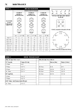
the torque value shown in the TORQUE SETTING TABLE later in this
section.
This compressor is equipped with a variable speed fan clutch that
requires no periodic maintenance.
The fan belt(s) should be checked regularly for wear and correct
tensioning.
FUEL SYSTEM
The fuel tank should be filled daily or every eight hours. To minimise
condensation in the fuel tank(s), it is advisable to top up after the
machine is shut down or at the end of each working day. At six month
intervals drain any sediment or condensate that may have
accumulated in the tank(s).
FUEL FILTER MAINTENANCE
This compressor is equipped with 2 fuel filters in series to be replaced
at every 500 hour interval or sooner if required.
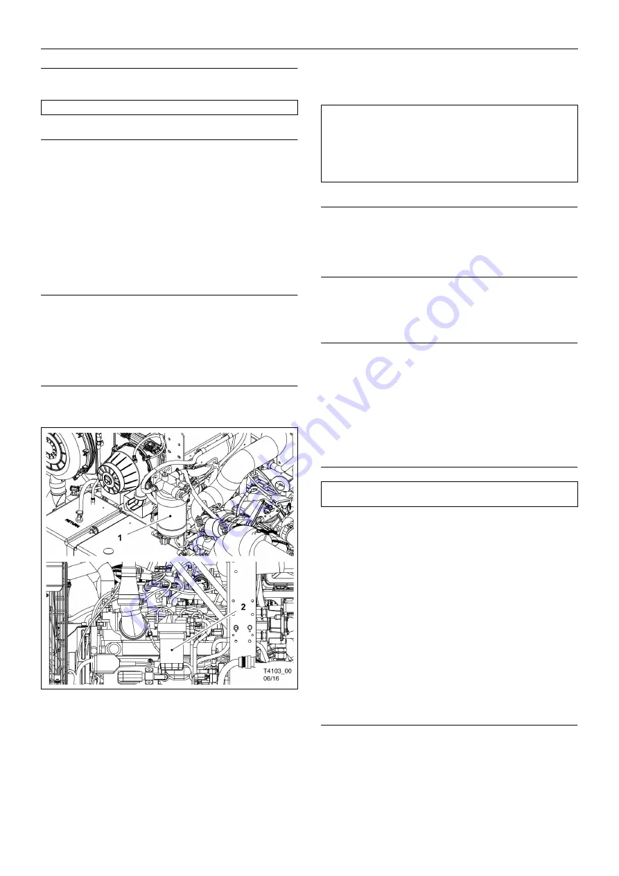
1. Fuel Filter / Water Separator (10 microns).
2. Final Fuel Filter / Water Separator (3 microns).
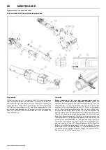
Fuel Filter / Water Separator
Mounted to the DEF module bracket, this filter is capable of separating
water from fuel and will filter solid contaminants to 10 microns in size.
Replace:
Remove the Water In Fuel sensor connector from the bottom
of the filter element, remove and discard the filter. Install a new element
taking care all seals are in place, install the sensor connector.
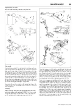
Final Fuel Filter / Water Separator
The final fuel filter (3 micron) is mounted on the engine. For
maintenance details, refer to the engine manual.
FUEL FILTER WATER SEPARATOR
The fuel filter water separator contains a filter element which should be
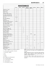
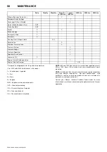
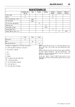
replaced at regular intervals (see the SERVICE/MAINTENANCE
CHART).
CHARGE COOLER PIPEWORK
Inspect all hoses and clips on the charge cooler pipe work.
Engine damage will occur if the charge cooling system leaks.
HOSES
All components of the engine cooling air intake system should be
checked periodically to keep the engine at peak efficiency.
At the recommended intervals, (see the SERVICE/MAINTENANCE
CHART), inspect all of the intake lines to the air filter, and all flexible
hoses used for air lines, oil lines and fuel lines.
Periodically inspect all pipework for cracks, leaks, etc. and replace
immediately if damaged.
ELECTRICAL SYSTEM
When removing connectors from electrical devices and sensors,
inspect the terminals to ensure they have electrical grease on them. If
electrical grease is not present or very minimal, then add a small
amount of electrical grease (Doosan Part No. 22409114) to the
terminals. Dirty and or corroded electrical terminals can be cleaned
using electrical contact cleaner.
Inspect the safety shutdown system switches and the instrument panel
relay contacts for evidence of arcing and pitting. Clean where
necessary.
Check the mechanical action of the components.
Check the security of electrical terminals on the switches and relays i.e.
nuts or screws loose, which may cause local hot spot oxidation.
Inspect the components and wiring for signs of overheating i.e.
discolouration, charring of cables, deformation of parts, acrid smells
and blistered paint.
BATTERY
Keep the battery terminals and cable clamps clean and lightly coated
with petroleum jelly to prevent corrosion.
The retaining clamp should be kept tight enough to prevent the battery
from moving.
CAUTION:
NEVER clean by blowing air inwards.
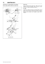
WARNING: The Primary as well as Secondary filter elements
may be filled with the appropriate quality of fuel from a clean
source. NEVER fill the Final fuel filter before installing.
The correct procedure would be to fill Primary and Secondary
filters with clean fuel, leave the Final filter empty and prime the
system using the hand prime pump on the Primary filter head.
WARNING: Always disconnect the battery switch before
performing any maintenance or service.
Содержание 10/104
Страница 2: ......
Страница 4: ......
Страница 11: ...ISO SYMBOLS 7 7 124 10 104 10 124 14 114 14 84 Replace any cracked protective shield ...
Страница 83: ...MAINTENANCE 79 7 124 10 104 10 124 14 114 14 84 ...
Страница 84: ...80 MAINTENANCE 7 124 10 104 10 124 14 114 14 84 ...
Страница 92: ...88 MACHINE SYSTEMS 7 124 10 104 10 124 14 114 14 84 ...
Страница 108: ......
Страница 109: ......
Страница 110: ...Doosan Bobcat EMEA s r o U Kodetky 1810 263 12 Dobříš Czech Republic www doosanportablepower eu ...

