REPAIR
27080 Issue 1 Sept 98
8--19
(14) Refit the cover over the upper part of the head.
The replacement is now complete. Note that to work correctly, the
gutter sensor must be completely electrically isolated except for its
wiring connections. Check the sensor to ensure that at no point does the
metal inner tube of the sensor make electrical contact with the chassis,
etc.
Carry out the gutter alignment procedure.
Gutter Alignment
CAUTION
The print head must be securely mounted over a large
beaker, tissue must be ready to clear up escaping ink
and protective clothing must be worn.
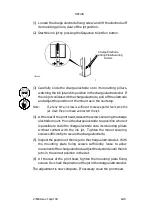
The jet should enter the gutter just inside the gutter tube wall as shown
in the diagram. Align the gutter as follows.
The printer must be shut down, but ready to run, and the print head
must be removed from its holster.
(1) Start up the printer.
(2) Check the position of the jet with respect to the deflector plates.
The jet should be parallel with the deflector plates and 1mm from
the plate on the gutter side (see diagram). If necessary, align the jet
(see Pg. 7--15).
(3) Shut down the printer. Remove the screw securing the deflector
plate over the gutter, to improve access to the screws securing the
gutter pipe. Move the deflector plate to a secure position away
from the ink jet.
(4) Slacken the gutter pipe securing screws sufficiently for the pipe to
be held in place, but adjustable in position.
(5) Start up the printer and adjust the gutter so that the jet enters the
gutter at the correct position (see diagram).
(6) Shut down the printer and tighten the screws to secure the gutter
pipe.
(7) Refit and secure the deflector plate.
The printer should be started up to check that the jet alignment is
correct.
Содержание A-SERIES
Страница 1: ...DOMINO A SERIES INK JET PRINTER OPERATION AND MAINTENANCE MANUAL ...
Страница 6: ... 6 27080 Issue 1 Sept 98 ...
Страница 8: ... 8 27080 Issue 1 Sept 98 ...
Страница 10: ... 10 27080 Issue 1 Sept 98 ...
Страница 12: ...HEALTH AND SAFETY 1 2 27080 Issue 1 August 98 ...
Страница 18: ...HEALTH AND SAFETY 1 8 27080 Issue 1 August 98 ...
Страница 20: ......
Страница 21: ......
Страница 22: ......
Страница 36: ...OPERATION 3 2 27080 Issue 1 August 98 ...
Страница 55: ...DISPLAY MESSAGES AND FAULT FINDING 4 2 27080 Issue 1 August 98 ...
Страница 76: ...REFERENCE 5 4 27080 Issue 1 August 98 ...
Страница 136: ...PRINTER DESCRIPTION 6 20 27080 Issue 1 September 98 ...
Страница 137: ...DESCRIPTION 27080 Issue 1 August 98 6 21 Wiring Diagram 37700W Iss 1 PELTI ER ...
Страница 138: ...DESCRIPTION 6 22 27080 Issue 1 August 98 ...
Страница 140: ...MAINTENANCE 7 2 27080 Issue 1 Sept 98 ...
Страница 142: ...MAINTENANCE 7 4 27080 Issue 1 Sept 98 ...
Страница 156: ...MAINTENANCE 7 18 27080 Issue 1 Sept 98 ...
Страница 158: ...REPAIR 8 2 27080 Issue 1 Sept 98 ...
Страница 192: ...REPAIR 8 36 27080 Issue 1 Sept 98 ...
Страница 198: ...SPARES AND ACCESSORIES 9 6 27080 Issue 1 Sept 98 5 6 7 8 2 3 1 4 9 Print Head General Detail CA002 1 4 4 ...
Страница 200: ...SPARES AND ACCESSORIES 9 8 27080 Issue 1 Sept 98 Ink System General 2 3 5 6 7 8 9 10 11 12 1 MG045_1 4 ...
Страница 202: ...SPARES AND ACCESSORIES 9 10 27080 Issue 1 Sept 98 Ink Management Block 1 2 3 4 5 6 7 8 9 10 6 MG046_1 ...
Страница 204: ...SPARES AND ACCESSORIES 9 12 27080 Issue 1 Sept 98 Electronics Door Assembly A300 A200 1 2 3 4 5 6 7 8 9 MG060_2 ...
Страница 206: ...SPARES AND ACCESSORIES 9 14 27080 Issue 1 Sept 98 Electronics Door Assembly A100 1 2 3 4 5 6 7 A1003_2 ...
Страница 208: ...SPARES AND ACCESSORIES 9 16 27080 Issue 1 Sept 98 Electronics Inner Door 1 2 3 4 5 6 7 ...
Страница 210: ...SPARES AND ACCESSORIES 9 18 27080 Issue 1 Sept 98 Electronics Cabinet MG067_2 1 2 3 4 5 6 7 8 10 11 12 13 14 15 9 ...
Страница 212: ...SPARES AND ACCESSORIES 9 20 27080 Issue 1 Sept 98 ...
Страница 214: ...OPTIONS 10 2 27080 Issue 1 Sept 98 ...
Страница 240: ...OPTIONS 10 28 27080 Issue 1 Sept 98 ...
Страница 242: ...APPENDIX A INSTALLATION A 2 27080 Issue 1 Sept 98 ...
Страница 261: ...APPENDIX B COMPRESSOR DRIVEN AIRDRYER B 2 20950 Issue 1 April 98 ...
Страница 300: ...APPENDIX B COMPRESSOR DRIVEN AIRDRYER 20950 Issue 1 April 98 B 41 37710W Issue 1 Airdryer Wiring Diagram ...
Страница 301: ...APPENDIX B COMPRESSOR DRIVEN AIRDRYER B 42 20950 Issue 1 April 98 AD032_1 Airdryer Power Diagram ...
Страница 302: ...APPENDIX B COMPRESSOR DRIVEN AIRDRYER 20950 Issue 1 April 98 B 43 This page is intentionally blank ...
Страница 310: ...20951 Issue 1 Apr 98 B 1 APPENDIX B AIR DRIVEN AIRDRYER AMENDMENT RECORD Amendment Date All pages at Issue 1 Apr 98 ...
Страница 311: ...APPENDIX B A SERIES AIR DRIVEN AIRDRYER B 2 20951 Issue 1 Apr 98 ...
Страница 313: ...APPENDIX B A SERIES AIR DRIVEN AIRDRYER B 4 20951 Issue 1 Apr 98 ...
Страница 330: ...APPENDIX B A SERIES AIR DRIVEN AIRDRYER 20951 Issue 1 Apr 98 B 21 37709W Issue 1 Airdryer Wiring Diagram ...
Страница 331: ...APPENDIX B A SERIES AIR DRIVEN AIRDRYER B 22 20951 Issue 1 Apr 98 Airdryer Power Diagram AD033_1 ...
Страница 332: ...APPENDIX B A SERIES AIR DRIVEN AIRDRYER 20951 Issue 1 Apr 98 B 23 This page is intentionally blank ...


