PRINTER DESCRIPTION
27080 Issue 1 September 98
6--3
PRINTER DESCRIPTION
PRINT HEAD
General Principles
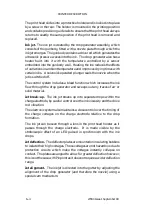
Each printed character consists of a dot
matrix made up of lines, or strokes, of ink
drops. The ink drops in each stroke are
spaced apart by electronic deflection and the
strokes are spaced apart by the movement of
the print surface under the head.
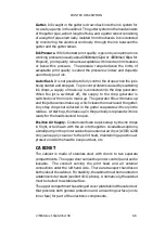
Inside the print head, ink is supplied under
pressure to the drop generator, and emerges
through a small nozzle as a very fine jet. The
drop generator contains a drive rod which
creates ultrasonic pressure waves in the ink,
making the jet break up into a stream of
separate drops shortly after leaving the
nozzle.
The break--up is adjusted to occur within the
charge electrode, where each ink drop is
given an electrostatic charge by putting a
voltage onto the charge electrode as the drop
breaks off. The size of the charge on the ink
drop depends upon the voltage on the charge
electrode.
The ink drops then pass through the
electrostatic field set up between between
two high voltage deflector plates.
The
direction of flight of each charged ink drop is
deflected by an amount dependent upon the size of the charge.
Ink drops not required for printing are not given electrostatic charges
and are collected in the gutter.
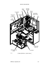
Details
The print head components are mounted on a rigid chassis, with a fully
enclosed top section containing the connections between the print head
and conduit wiring.
Ink
Drops
Unused
Positions
Stroke
TP1130--1
Drop
Generator
Charge
Electrode
Nozzle
Plate
Deflector
Plates
Gutter
TP1141--5
Содержание A-SERIES
Страница 1: ...DOMINO A SERIES INK JET PRINTER OPERATION AND MAINTENANCE MANUAL ...
Страница 6: ... 6 27080 Issue 1 Sept 98 ...
Страница 8: ... 8 27080 Issue 1 Sept 98 ...
Страница 10: ... 10 27080 Issue 1 Sept 98 ...
Страница 12: ...HEALTH AND SAFETY 1 2 27080 Issue 1 August 98 ...
Страница 18: ...HEALTH AND SAFETY 1 8 27080 Issue 1 August 98 ...
Страница 20: ......
Страница 21: ......
Страница 22: ......
Страница 36: ...OPERATION 3 2 27080 Issue 1 August 98 ...
Страница 55: ...DISPLAY MESSAGES AND FAULT FINDING 4 2 27080 Issue 1 August 98 ...
Страница 76: ...REFERENCE 5 4 27080 Issue 1 August 98 ...
Страница 136: ...PRINTER DESCRIPTION 6 20 27080 Issue 1 September 98 ...
Страница 137: ...DESCRIPTION 27080 Issue 1 August 98 6 21 Wiring Diagram 37700W Iss 1 PELTI ER ...
Страница 138: ...DESCRIPTION 6 22 27080 Issue 1 August 98 ...
Страница 140: ...MAINTENANCE 7 2 27080 Issue 1 Sept 98 ...
Страница 142: ...MAINTENANCE 7 4 27080 Issue 1 Sept 98 ...
Страница 156: ...MAINTENANCE 7 18 27080 Issue 1 Sept 98 ...
Страница 158: ...REPAIR 8 2 27080 Issue 1 Sept 98 ...
Страница 192: ...REPAIR 8 36 27080 Issue 1 Sept 98 ...
Страница 198: ...SPARES AND ACCESSORIES 9 6 27080 Issue 1 Sept 98 5 6 7 8 2 3 1 4 9 Print Head General Detail CA002 1 4 4 ...
Страница 200: ...SPARES AND ACCESSORIES 9 8 27080 Issue 1 Sept 98 Ink System General 2 3 5 6 7 8 9 10 11 12 1 MG045_1 4 ...
Страница 202: ...SPARES AND ACCESSORIES 9 10 27080 Issue 1 Sept 98 Ink Management Block 1 2 3 4 5 6 7 8 9 10 6 MG046_1 ...
Страница 204: ...SPARES AND ACCESSORIES 9 12 27080 Issue 1 Sept 98 Electronics Door Assembly A300 A200 1 2 3 4 5 6 7 8 9 MG060_2 ...
Страница 206: ...SPARES AND ACCESSORIES 9 14 27080 Issue 1 Sept 98 Electronics Door Assembly A100 1 2 3 4 5 6 7 A1003_2 ...
Страница 208: ...SPARES AND ACCESSORIES 9 16 27080 Issue 1 Sept 98 Electronics Inner Door 1 2 3 4 5 6 7 ...
Страница 210: ...SPARES AND ACCESSORIES 9 18 27080 Issue 1 Sept 98 Electronics Cabinet MG067_2 1 2 3 4 5 6 7 8 10 11 12 13 14 15 9 ...
Страница 212: ...SPARES AND ACCESSORIES 9 20 27080 Issue 1 Sept 98 ...
Страница 214: ...OPTIONS 10 2 27080 Issue 1 Sept 98 ...
Страница 240: ...OPTIONS 10 28 27080 Issue 1 Sept 98 ...
Страница 242: ...APPENDIX A INSTALLATION A 2 27080 Issue 1 Sept 98 ...
Страница 261: ...APPENDIX B COMPRESSOR DRIVEN AIRDRYER B 2 20950 Issue 1 April 98 ...
Страница 300: ...APPENDIX B COMPRESSOR DRIVEN AIRDRYER 20950 Issue 1 April 98 B 41 37710W Issue 1 Airdryer Wiring Diagram ...
Страница 301: ...APPENDIX B COMPRESSOR DRIVEN AIRDRYER B 42 20950 Issue 1 April 98 AD032_1 Airdryer Power Diagram ...
Страница 302: ...APPENDIX B COMPRESSOR DRIVEN AIRDRYER 20950 Issue 1 April 98 B 43 This page is intentionally blank ...
Страница 310: ...20951 Issue 1 Apr 98 B 1 APPENDIX B AIR DRIVEN AIRDRYER AMENDMENT RECORD Amendment Date All pages at Issue 1 Apr 98 ...
Страница 311: ...APPENDIX B A SERIES AIR DRIVEN AIRDRYER B 2 20951 Issue 1 Apr 98 ...
Страница 313: ...APPENDIX B A SERIES AIR DRIVEN AIRDRYER B 4 20951 Issue 1 Apr 98 ...
Страница 330: ...APPENDIX B A SERIES AIR DRIVEN AIRDRYER 20951 Issue 1 Apr 98 B 21 37709W Issue 1 Airdryer Wiring Diagram ...
Страница 331: ...APPENDIX B A SERIES AIR DRIVEN AIRDRYER B 22 20951 Issue 1 Apr 98 Airdryer Power Diagram AD033_1 ...
Страница 332: ...APPENDIX B A SERIES AIR DRIVEN AIRDRYER 20951 Issue 1 Apr 98 B 23 This page is intentionally blank ...

