REPAIR
27080 Issue 1 Sept 98
8--17
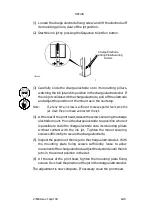
(8) Pass the deflector plate wiring along the printhead chassis and up
through the hole in the bulkhead seal (see step (4)) into the upper
part of the head. Carefully push the cable gland on the wiring into
the bulkhead seal.
(9) Fit heatshrink sleeving onto the deflector plate wires and connect
the wires into the conduit wiring (see step (2)). Use a heat gun to
tighten the heatshrink sleeving around the connectors.
(10) Refit the cover over the upper part of the head.
Gutter Tube and Sensor Replacement
The printer must be shut down and the print head removed from its
holster.
(1) Remove the cover over the upper part of the head by:
(a) removing the four screws in the sides,
(b) removing the two screws at the top,
(c) carefully pulling the sides away from the chassis and removing
the cover.
(2) Trace the wires from the gutter sensor to their connections at the
conduit wiring in the upper part of the head (see pg. 8--5).
(3) Cut the heatshrink sleeving around the connections and disconnect
the sensor wires.
(4) Trace the wires to their cable gland in the bulkhead seal. Carefully
push the cable gland out of the bulkhead seal in the direction of the
gutter sensor.
(5) At the rear of the print head, unscrew the two screws securing the
drop generator. These screws are captive and will remain in place.
Lift the drop generator away from the print head chassis
sufficiently for the gutter sensor to be removed.
(6) Remove the screw securing the deflector plate over the gutter
sensor. Move the deflector plate to one side.
(7) Remove the four screws securing the gutter block to the chassis.
(8) Disconnect the gutter sensor pipe at its connection to the conduit
gutter tube near the seal plate and remove the gutter block and the
gutter sensor from the print head as a single assembly.
Содержание A-SERIES
Страница 1: ...DOMINO A SERIES INK JET PRINTER OPERATION AND MAINTENANCE MANUAL ...
Страница 6: ... 6 27080 Issue 1 Sept 98 ...
Страница 8: ... 8 27080 Issue 1 Sept 98 ...
Страница 10: ... 10 27080 Issue 1 Sept 98 ...
Страница 12: ...HEALTH AND SAFETY 1 2 27080 Issue 1 August 98 ...
Страница 18: ...HEALTH AND SAFETY 1 8 27080 Issue 1 August 98 ...
Страница 20: ......
Страница 21: ......
Страница 22: ......
Страница 36: ...OPERATION 3 2 27080 Issue 1 August 98 ...
Страница 55: ...DISPLAY MESSAGES AND FAULT FINDING 4 2 27080 Issue 1 August 98 ...
Страница 76: ...REFERENCE 5 4 27080 Issue 1 August 98 ...
Страница 136: ...PRINTER DESCRIPTION 6 20 27080 Issue 1 September 98 ...
Страница 137: ...DESCRIPTION 27080 Issue 1 August 98 6 21 Wiring Diagram 37700W Iss 1 PELTI ER ...
Страница 138: ...DESCRIPTION 6 22 27080 Issue 1 August 98 ...
Страница 140: ...MAINTENANCE 7 2 27080 Issue 1 Sept 98 ...
Страница 142: ...MAINTENANCE 7 4 27080 Issue 1 Sept 98 ...
Страница 156: ...MAINTENANCE 7 18 27080 Issue 1 Sept 98 ...
Страница 158: ...REPAIR 8 2 27080 Issue 1 Sept 98 ...
Страница 192: ...REPAIR 8 36 27080 Issue 1 Sept 98 ...
Страница 198: ...SPARES AND ACCESSORIES 9 6 27080 Issue 1 Sept 98 5 6 7 8 2 3 1 4 9 Print Head General Detail CA002 1 4 4 ...
Страница 200: ...SPARES AND ACCESSORIES 9 8 27080 Issue 1 Sept 98 Ink System General 2 3 5 6 7 8 9 10 11 12 1 MG045_1 4 ...
Страница 202: ...SPARES AND ACCESSORIES 9 10 27080 Issue 1 Sept 98 Ink Management Block 1 2 3 4 5 6 7 8 9 10 6 MG046_1 ...
Страница 204: ...SPARES AND ACCESSORIES 9 12 27080 Issue 1 Sept 98 Electronics Door Assembly A300 A200 1 2 3 4 5 6 7 8 9 MG060_2 ...
Страница 206: ...SPARES AND ACCESSORIES 9 14 27080 Issue 1 Sept 98 Electronics Door Assembly A100 1 2 3 4 5 6 7 A1003_2 ...
Страница 208: ...SPARES AND ACCESSORIES 9 16 27080 Issue 1 Sept 98 Electronics Inner Door 1 2 3 4 5 6 7 ...
Страница 210: ...SPARES AND ACCESSORIES 9 18 27080 Issue 1 Sept 98 Electronics Cabinet MG067_2 1 2 3 4 5 6 7 8 10 11 12 13 14 15 9 ...
Страница 212: ...SPARES AND ACCESSORIES 9 20 27080 Issue 1 Sept 98 ...
Страница 214: ...OPTIONS 10 2 27080 Issue 1 Sept 98 ...
Страница 240: ...OPTIONS 10 28 27080 Issue 1 Sept 98 ...
Страница 242: ...APPENDIX A INSTALLATION A 2 27080 Issue 1 Sept 98 ...
Страница 261: ...APPENDIX B COMPRESSOR DRIVEN AIRDRYER B 2 20950 Issue 1 April 98 ...
Страница 300: ...APPENDIX B COMPRESSOR DRIVEN AIRDRYER 20950 Issue 1 April 98 B 41 37710W Issue 1 Airdryer Wiring Diagram ...
Страница 301: ...APPENDIX B COMPRESSOR DRIVEN AIRDRYER B 42 20950 Issue 1 April 98 AD032_1 Airdryer Power Diagram ...
Страница 302: ...APPENDIX B COMPRESSOR DRIVEN AIRDRYER 20950 Issue 1 April 98 B 43 This page is intentionally blank ...
Страница 310: ...20951 Issue 1 Apr 98 B 1 APPENDIX B AIR DRIVEN AIRDRYER AMENDMENT RECORD Amendment Date All pages at Issue 1 Apr 98 ...
Страница 311: ...APPENDIX B A SERIES AIR DRIVEN AIRDRYER B 2 20951 Issue 1 Apr 98 ...
Страница 313: ...APPENDIX B A SERIES AIR DRIVEN AIRDRYER B 4 20951 Issue 1 Apr 98 ...
Страница 330: ...APPENDIX B A SERIES AIR DRIVEN AIRDRYER 20951 Issue 1 Apr 98 B 21 37709W Issue 1 Airdryer Wiring Diagram ...
Страница 331: ...APPENDIX B A SERIES AIR DRIVEN AIRDRYER B 22 20951 Issue 1 Apr 98 Airdryer Power Diagram AD033_1 ...
Страница 332: ...APPENDIX B A SERIES AIR DRIVEN AIRDRYER 20951 Issue 1 Apr 98 B 23 This page is intentionally blank ...


