17
Installation
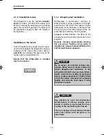
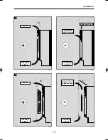
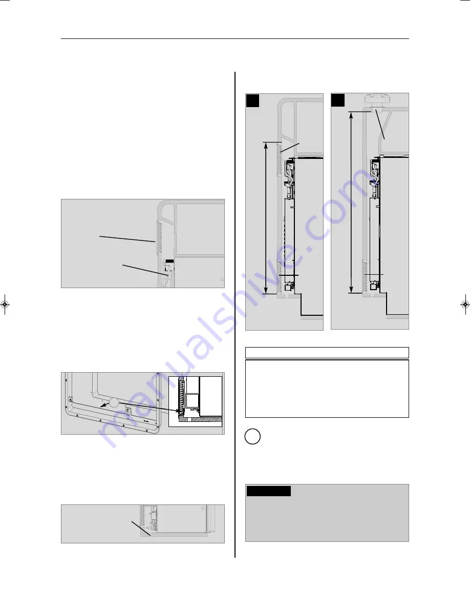
4.3 Installing the ventilation system
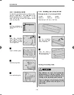
Fig. 21
The upper ventilation grille should be posi-
tioned as high as possible above the con-
denser (Fig. 19) .
Install the lower ventilation grille at floor
level of the vehicle (Fig. 20)
, allowing unburnt
gas (heavier than air) to escape directly into
the open air.
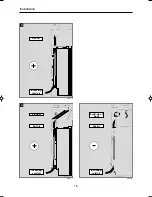
The gas burner must be loca-
ted above the edge (1) .
Should this arrangement prove impossible,
a ventilation aperture must be introduced
by the manufacturer of the vehicle into the
recess floor in order to avoid the accumula-
tion of unburnt gas on the floor (Fig. 21).
Fig. 20
1
Ventilation aperture
The ventilation grilles must have an open
cross-section of at least 400cm².
This is
achieved by using the Dometic LS 300 absor-
ber ventilation and air extraction system
which has been tested and approved for this
purpose.
Fig. 19
LS300
Cooling unit /
condenser
An installation other than described will
reduce the cooling capacity and jeopardi-
se the manufacturer's warranty/product
liability.
CAUTION!
Correct mounting of the lower ventilation gril-
le facilitates access to the connections and
functional parts during maintenance.
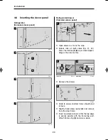
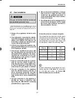
4.3.1 Position of the ventilation grilles
Minimum height of ventilation
H
1.
Upper and lower vent grille LS 300
1300 mm
2.
Roof exhaust R500, lower vent grille LS 300
1250 mm
i
Abb. 23
Minimum height of ventilation
H
LS300
1.
LS300
Minimum height of ventilation
H
LS300
2.
R 500
Abb. 22
289 0318-80_EN_RMF-C_85xx-Installation_N1_Layout 1 10.09.2013 12:50 Seite 17
Содержание RMF8500
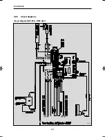
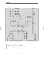
Страница 28: ...26 Circuit diagram RMF 85x1 RMF 85x5 Fig 51 1 C D B A Installation 4 8 5 Circuit diagrams...
Страница 34: ...4 Dometic GmbH 2013 nderungen vorbehalten Dometic GmbH In der Steinwiese 16 D 57074 Siegen www dometic com...
Страница 46: ...16 Einbau Abb 16 3 Abb 17 4 Luftkanal Warmluft Kaltluft Warmluft Kaltluft 3 Abb 18 Warmluft Kaltluft W rmestau...
Страница 56: ...26 Schaltschema RMF 85x1 RMF 85x5 Abb 51 1 C D B A Einbau 4 8 5 Schaltschemata...
Страница 59: ...29 Installation...

