


10
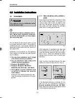
4.0 Installation instructions
4.1
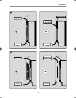
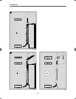
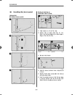
Installation
Installation
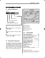
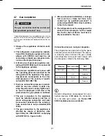
Fig. 3
Fig. 4
OK
min. 25 mm
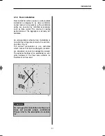
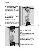
4.1.1 Side installation with ventilation
grilles
If possible, do not install the refrigerator on the
side of the entrance door. An awning or a
caravan annex tent is often installed on this
side. This complicates evacuation of combu-
stion gases and heat through the ventilation
grilles (loss in cooling performance)!
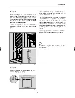
If the refrigerator is installed on the same side
of the vehicle as the entrance door, it is desi-
rable that the door does not cover the refrige-
rator's vents. Otherwise ventilation could be
impaired which causes a loss in cooling per-
formance.
There must be a distance between the door
and the air vents of at least 25 mm! (Fig. 4).
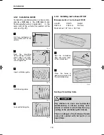
If the door/grille distance is between 25 mm
and 45 mm, we recommend installing a
Dometic ventilation kit (
item no. 241 2985 -
01)
to achieve an optimal cooling performance
in high ambient temperatures.
Fig. 2
OK
The unit and the exhaust duct system must be
in principle installed so that it is accessible for
maintenance work, can be easily installed and
dismantled and removed from the vehicle wit-
hout great effort.
Installation and connection of the appliance
must comply with the latest technical regulati-
ons, as follows:
n
The electrical installation must comply
with national and local regulations.
n
The gas installation must comply with
national and local regulations.
n
European Standard EN 1949
n
European Standards EN 60335-1,
EN 60335-2-24, EN 1648-1 , EN 1648-2
n
The appliance must be installed in such
a way that it is shielded from excessive
heat radiation.
Excessive heat impairs performance and
raises the energy consumption of the refri-
gerator!
Deviations from these installation instruc-
tions without prior notification of Dometic
result in Dometic GmbH's warranty obliga-
tions becoming void!
The appliance may be installed by autho-
rised personnel only!
WARNING!
i
289 0318-80_EN_RMF-C_85xx-Installation_N1_Layout 1 10.09.2013 12:48 Seite 10
Содержание RMF8500
Страница 28: ...26 Circuit diagram RMF 85x1 RMF 85x5 Fig 51 1 C D B A Installation 4 8 5 Circuit diagrams...
Страница 34: ...4 Dometic GmbH 2013 nderungen vorbehalten Dometic GmbH In der Steinwiese 16 D 57074 Siegen www dometic com...
Страница 46: ...16 Einbau Abb 16 3 Abb 17 4 Luftkanal Warmluft Kaltluft Warmluft Kaltluft 3 Abb 18 Warmluft Kaltluft W rmestau...
Страница 56: ...26 Schaltschema RMF 85x1 RMF 85x5 Abb 51 1 C D B A Einbau 4 8 5 Schaltschemata...
Страница 59: ...29 Installation...