15
gas mode
note: all current dometic control boards are
3 try systems in the gas mode. there is a
2 minute purge cycle between each trial for
ignition. flame failure could take 6 to 7 min-
utes.
Verify that the following components are good, upper cir-
cuit control boards, thermistor, wire harness and 3-amp
fuse. First, check for voltage during
trial-for-ignition
at
Plug 3, Terminals 1 (white Wire -) and 2 (yellow wire +) to
the igniter and solenoid. If no voltage is present change
the circuit board. If voltage is present, check for volt-
age at the igniter and solenoid. If no voltage is present,
check the wires. To check the flame sense circuit of the
lower circuit board, operate the refrigerator on GAS and
measure the millivolts between J4 (NEGATIVE) terminal
and J10 (POSITIVE) connection from the thermocouple.
The thermocouple should produce 20 millivolts minimum.
Anything less than 20 millivolts will cause erratic gas op-
eration. The millivolts meter should read between 25 to
35 millivolts with the gas flame burning. When the power
module senses the loss of flame (thermocouple millivolts
below 13 MVDC) the 45 seconds trial for ignition period is
started. Turning the refrigerator OFF–ON while operating
in the gas mode may cause a check light.
note: a loose ground will create erratic or
no gas operation.
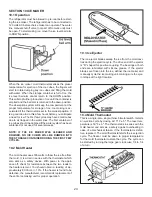
5.10 door Switch
The door switch is an open switch when the switch arm
is depressed (interior light should be off). When the re-
frigerator door is open the switch is closed (interior light
should be on). Check that the switch assembly is properly
aligned and that it is not broken. Check the switch assem-
bly for continuity. To do a continuity check, first be sure all
power is disconnected or OFF to the refrigerator. Second,
remove all wires from the switch assembly, then check the
switch. When the switch is depressed, there should not
be continuity. When the switch is NOT depressed, there
should be continuity. If any of these checks are incorrect,
replace the switch. After the check, be sure the switch as-
sembly is wired properly per the wiring diagram.
5.11 fuses
The 3 amp DC fuse is designed to protect the circuit board
from internal/external DC shorts. The 5 amp AC fuse is
designed to protect the integrity of the AC detection and
heater circuit from shorts. All fuses can be checked for
continuity. If a fuse blows don’t replace it until the problem
has been found. If a fuse blows there is a short or compo-
nent that has created the problem.
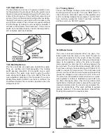
5.12 thermofuse
The RM3962/3762 cooling units have a Thermofuse lo-
cated on the boiler. The function of the thermofuse is to
shut down the control system in the event the cooling
unit over heats. On certain units the fuse can be reset
by pushing the button in the center. The thermofuse is a
non replaceable component of the cooling unit. When the
fuse pops it is normally an indication the cooling unit has
a problem and the cooling unit will have to be replaced.
The fuse can be checked for continuity.
Содержание RM3962
Страница 15: ...14 RM3762 RM3962...
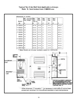
Страница 20: ...19 Typical Two Side Wall Vent Application Always Refer To Vent Instructions 3308666 xxx...
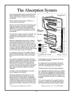
Страница 23: ...22...
Страница 28: ...27...
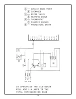
Страница 29: ...28 ICE MAKER TYPICAL WIRING DIAGRAM...
Страница 33: ...32...

