


26
this is an energized circuit. Shock can occur
if not tested properly. testing is to be done
by a qualified service technician.
10.9 Ice maker replacement
It may be necessary to replace the entire ice maker as-
sembly. Disconnect power to the appliance. Disconnect
the 4 pin connector from the ice maker unit. Check each
wire for continuity to make sure the wiring is good before
replacing the ice maker unit. If there is no continuity on
any of these wires, replace or repair them as necessary
and recheck the ice maker unit to determine whether the
problem was in the wiring or the unit itself. Remove the
three screws holding the unit to the plate. Before replac-
ing the ice maker assembly check the temperature in the
freezer. For the unit to cycle it should be 12 degrees or
cooler as the mold thermostat starts the cycle.
10.10 Water fill adjustment
The correct water level in the mold is important for the
proper production of ice. The size of the ice cubes de-
pends on the amount of water which enters the mold. The
cubes should be approximately 1/2” wide, 3/4” high and 2-
1/2” long. If the water overflows in the mold, first check to
see if the ice maker unit is level in the appliance. Next en-
sure that the appliance is installed level in the RV. If there
is still water overflow, adjustment of the water fill screw is
necessary. Locate the screw on the ice maker assembly.
Turn the screw as necessary toward the “+” or “—” side.
One full turn of the screw will make an 18 cc change in
the amount of water. DO NOT turn the screw more than
one full turn at a time. If the water level is too high, it can
also cause the ejector blades to become frozen in the ice.
Follow the procedures above to correct the problem.
this is an energized circuit. Shock can occur
if not tested properly. testing is to be done
by a qualified service technician.
10.11 Water Supply
To operate properly, the water pressure in the water sup-
ply line must be between 15 and 50 PSI. Lower water
pressure, water turned off, or obstructions or air in the wa-
ter line can cause low or no ice production. First check to
see that the water supply is fully turned on. Visually check
the line for kinks, etc. which might obstruct the flow of
water. To remove trapped air, loosen the connection at the
water solenoid valve of the appliance. Ensure that pres-
surized water is reaching this point, and bleed off any air
in the line. Retighten the connection, making sure there
are no leaks.
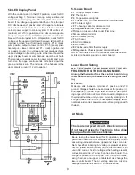
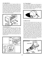
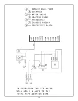
10.12 Wiring
Refer to the wiring diagram supplied with the unit you are
working on, and make sure all wiring connections are cor-
rect and tight. There are 4 wires coming from the ice maker.
BlacK:
Connected to incoming hot from AC pow-
er source. This could be split wire at the AC BLACK
at the circuit board or on a separate power cord.
WHIte:
Connected to either side of the water valve and
will split at the valve and hook-up to the incoming
WHIte
from the power source or separate cord.
green/yelloW:
Connected to chassis ground.
BroWn:
Connected to either side of water valve.
Содержание RM3962
Страница 15: ...14 RM3762 RM3962...
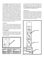
Страница 20: ...19 Typical Two Side Wall Vent Application Always Refer To Vent Instructions 3308666 xxx...
Страница 23: ...22...
Страница 28: ...27...
Страница 29: ...28 ICE MAKER TYPICAL WIRING DIAGRAM...
Страница 33: ...32...