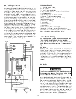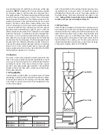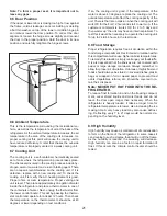
10
SectIon 4 dc Voltage
Clean Direct Current (DC) power is mandatory for high-
tech circuits to operate as designed. A battery will provide
straight line DC power. The converter and alternator pro-
duce DC power by a series of diodes that rectify alternat-
ing current to DC. The Dometic control system will only
tolerate up to 6 AC volts on the DC line. AC ripple can be
measured by a digital voltmeter set on the AC scale at the
main DC terminal block connections at the refer. Six volts
AC or less is acceptable. If AC volts exceed 6 on the DC
incoming line the power source should be cleaned up. AC
voltage in excess of 6 volts will affect the processor and
create erratic operation. When testing for AC ripple on
the DC line put a load on the converter. The operational
range of the unit is a minimum of 9.6 volts DC to a maxi-
mum of 22 volts DC. The unit will automatically shut down
at 22 volts DC volts or greater, and come back on when
voltage has decreased to 18 volts DC. The refrigerator
requires at least 9.6 volts DC for proper operation; how-
ever, the panel lights will continue to illuminate until volt-
age has dropped to 4 volts DC or below.
do not
use the
body or chassis of the RV as a substitute for either of the
two conductors. The refrigerator must be connected to
the battery circuit with two wires of adequate capacity to
avoid voltage drop. Proper polarity is crucial for refrigera-
tor operation.
no other electrical equipment or lighting
should be connected to the refrigerator circuit
. Just
because you can read volts does not mean you have the
amps to operate the control system. If relays buzz, lights
go dim or out during operation, this could indicate there is
a loose connection somewhere.
grounds
The operation of the Dometic refrigerator is also depen-
dent on good, clean ground connections. Loose or corrod-
ed ground terminals create a unknown resistance factor
that can affect the voltage detected by the Power Module.
A loose negative DC wire will create a negative millivolt
signal that the control board will pick up and create erratic
operation. Check the integrity of the grounds from the re-
frigerator all the way to the power source/battery. Clean or
tighten any suspicious looking connections.
note:
The DC terminal block below the control boards
should be cleaned and tightened at all 4 wires.
Main Terminal Block
The refrigerator is equipped with a grounded three-prong
plug for protection against shock hazards. It should be
plugged directly into a properly grounded three-prong re-
ceptacle. Do not cut or remove the grounding prong from
this plug! The free length of the cord is 2 feet and therefore
recommended that the receptacle be located to the left
side (opposite side of refrigerator burner assembly) of the
refrigerator (viewed from the rear). To allow easy access
through the vent door, place the receptacle 3” above the
refrigerator mounting floor. The cord should be routed to
avoid direct contact with the burner cover, flue cover or any
other components that could damage the cord insulation.
The refrigerator will not switch to another mode of opera-
tion until all AC power is lost.
SectIon 3 ac comPonentS
Heating element
The heating element is designed to deliver a predeter-
mined amount of heat to the cooling unit. To check a heat-
ing element, remove the heater leads from the printed
circuit board and measure for proper resistance across
the two leads with a properly calibrated ohm meter. This
check is to be done with the heating element at room tem-
perature. You should obtain the following readings ± 10%:
Model
Watts
Ohms
Amps
RM3762
325
44
2.7
RM3962
325
44
2.7
note: never over or under size the ac heater.
Содержание RM3962
Страница 15: ...14 RM3762 RM3962...
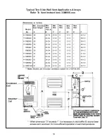
Страница 20: ...19 Typical Two Side Wall Vent Application Always Refer To Vent Instructions 3308666 xxx...
Страница 23: ...22...
Страница 28: ...27...
Страница 29: ...28 ICE MAKER TYPICAL WIRING DIAGRAM...
Страница 33: ...32...

