23
9.1 Internal Wiring
Check all wires and the connectors to ensure a proper
and tight connection. Also verify the refrigerator is wired
per the wiring diagram for the model you are working on.
(See applicable wiring diagrams for your model refrigera-
tor) A loose connection can create erratic operation. Al-
ways check the wires at the DC terminal block, two wires
in and two wires out.
SectIon 9 WIrIng
9.2 external Wiring
120 Volts ac connection:
The refrigerator is equipped
with a three prong (grounded) plug for protection against
shock hazards and should be plugged directly into a prop-
erly grounded three prong receptacle. DO NOT cut or re-
move the grounding prong from this plug.
12 Volt connection:
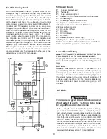
The connection is made to the ter-
minal block marked 12 volts DC. The control system is
connected to a battery/converter circuit and could draw
up to 3 amps at 12 volts DC. The refrigerator must be
connected to the battery circuit with two wires of adequate
capacity to avoid voltage drop. Proper polarity is crucial
for refrigerator operation. Don’t use the chassis for the
ground circuit.
A loose connection will create erratic op-
eration on gas and AC. The wires must be a dedicated cir-
cuit.
no other electrical equipment or lighting should
be connected to refrigerator circuit.
9.3 Wiring Schematics
To view typical wiring schematics look in the Lower Circuit
board testing section 5, page 14. All units should have a
specific schematic on the rear of that unit. To acquire the
proper one always have the product number when you
call or e-mail.
SectIon 10 error codes
The codes are displayed flashing ( alternating between
temperature and message) on the display.
No communication between display and power modules.
The control system will revert to full automatic operation
selecting the best energy source available with AC, GAS
priority. The temperature setting will be maintained at the
mid positions. The power module will continually attempt
to reestablish operation of the display module. Test Cable,
Upper LED display panel, Lower board, clean all grounds,
and try a different DC power source. If problem still exist
change lower control board.
e 0
e 1
Hardware fault in the gas operation system.
Test Upper and lower controls, Solenoid, wire harness,
clean all grounds and try a different DC power source.
A failure of the temperature sensor device or associated
electronic circuitry has occurred. If the connection to the
temperature sensor is faulty, the cooling unit runs continu-
ously ( over cool ) after 30 seconds delay at power on.
Test Thermistor.
SectIon 11 diagnostic mode
To perform a diagnostic test:
1.
Turn off the refrigerator. (press ON/OFF button)
2.
Press and hold the TEMP. SET button and then,
press the ON/OFF button.
3.
Release the TEMP. SET button. Press it again to
toggle the list of functions step by step.
e 2
1 All outputs off F
E 0 Communication Fault
E 2 Temperature sensor fault
2 Turn LAC
heater on
L H E 0 Communication Fault
0 N LAC heater on
Press the lamp switch. The
lamp should still be on.
3 Turn AC heat-
er on
A C E 0 Communication Fault
0 N AC heater on
“ ” AC heater off, AC not
available
4 D+ status (if
D+ is con-
nected) Not
available on
all models
d P E 0 Communication Fault
0 N D+ high
“ ” D+ low
5 Run gas (one
attemp only)
L P E 0 Communication Fault
E 1 Igniter & valve off, gas
hardware fault
0 N Igniter & valve on
F L Igniter off &valve on flame
detected
“ ” Igniter & valve off, gas
problem (check gas) ( If
flame is not ignited within
45 seconds)
number
test function
test Indication
test results Indication
11.1 diagnostic test
Содержание RM3962
Страница 15: ...14 RM3762 RM3962...
Страница 20: ...19 Typical Two Side Wall Vent Application Always Refer To Vent Instructions 3308666 xxx...
Страница 23: ...22...
Страница 28: ...27...
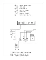
Страница 29: ...28 ICE MAKER TYPICAL WIRING DIAGRAM...
Страница 33: ...32...


