background image

3

INSTALLATION ELECTRICAL CONNECTION

GENERAL INSTRUCTIONS 115 Volts A C

The refrigerators outlined hereon have been de-

sign certified under ANS Z 21.19 Refrigerators
by the American Gas Association for installation

in a mobile home or recreational vehicle and are

approved by the Canadian Gas Association. The
certifications are, however, contingent on the
installation being made in accordance with the
following instructions.

The installation must in the USA conform with:

The refrigerator is equipped with a three
prong (grounded) plug for protection against

shock hazard and should be plugged directly
into a properly grounded three prong recept-

acle. Do not cut or remove the grounding
prong from this plug. The cord should be

routed to avoid coming in contact with the

burner cover, flue cover or other hot com-
ponents.

12 Volts VDC optional for certain models

1. National Fuel Gas Code Z223.1-1974

2. Mobile Homes A119.1-1972
3. Recreational Vehicles A119.2-1970

The unit must be electrically grounded in accor-
dance with the National Electrical Code ANSI, CI-

1968, when installed if an external alternating
current electrical source is utilized.

4. Any applicable local code

On "Tri-Pover units there is an additional

terminal block marked "12 V". The refrigera-
tor must be connected to the battery circuit

with two wires of adequate capacity to avoid

voltage drop. The wire gage should be chosen

with consideration to the wire length in

accordance with the following tabel: The 12 V
circuit must be fused with an appropriate
fuse.

In Canada

TABLE

1. Standard CGA lO.l/CSA  2240.4 gas equipped

mobile housing and recreational vehicles

2. Standard CSA Z240.6.1 electrical requirements

Maximum two conductor wire length for different
AWG numbers.

for mobile housing

Maximum two conductor wire length in feet

3. Standard CSA Z240.6.2/C22.2 No 148 electrical

requirements for recreational vehicles AWG

Ventilation

The installation shall be made in such a manner
as to separate the combustion system from the

living space of the mobile home or recreational

vehicle. Openings for air supply or for venting

of combustion products shall have a minimum di-
mension of not less than l/4 inch.

14 10
12 17
10 27

8 43
6 69
4 110

Proper installation requires one lower fresh air

intake and one upper exhaust vent. The ventila-
tion kits shown in this instruction booklet have
been certified for use with the refrigerator mo-
dels listed in the tables. The ventilation kits

must be installed and used without modification.

An opening towards the outside at floor level in

the refrigerator compartment must be provided for
ventilation of heavier-than-air fuel gases. The

lower vent of the recommended kits is provided

with proper size opening.
For ready serviceability of the burner and con-

trol manifold parts of the refrigerator the lower

side vent is fitted with a lift-out panel which

provides an adequate access opening.

Do not use the body or chassis of the
vehicle as a substitute for either of the two

conductors. No other electrical equipment
or lighting should be connected to the re-
frigerator circuit. The refrigerator will draw

from l0-21 Amps at 12 Volt depending on model.

CAUTION

Do not operate the refrigerator on 12 Volt when

the vehicle is parked. You will run out of

battery in a rather short time.

GAS CONNECTION

Hook-up to the gas supply line is accomplish-

ed at the manual gas valve, which is furnish-
ed with a 3/8" SAE (UNF 5/8"-18)  male flare
connection. All completed connections should
be checked for leaks with soapy water.
The gas supply system must incorporate a
pressure regulator to maintain a supply pres-

sure of not more than 11 inches water gage.

F i g . 1  

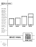
RM360

120w

RM460

RM660

RM760

135w 175w 250W

9 7 5

15 12 8
25 19 13
40 31 22
64 49 34

102 79 55

Содержание RM360

Страница 1: ...P 7895 SW Hunziker Rd Portland OR 97223 Phone 503 620 9510 DOMETIC SALES CORP 2920 Avenue E East Alington TX 76011 P h o n e 817 277 72 1 DOMETIC SALES CORP East Oak Ridge Dr Rt 9 Box I7 A Hagerstown...

Страница 2: ...e 10 The absorption cooling unit page 10 Operation analysis for cooling unit page 10 Cooling unit replacement RM360 460 660 page 11 Cooling unit replacement RM760 page 12 The gas electric equipment pa...

Страница 3: ...r wire length in feet 3 Standard CSA Z240 6 2 C22 2 No 148 electrical requirements for recreational vehicles AWG Ventilation The installation shall be made in such a manner as to separate the combusti...

Страница 4: ...osure as shown in Fig 2 Be careful not to damage the sealing strip applied to the floor of the enclosure when the refrigerator must be blocked The heat produced at the rear of the refrigerator will ot...

Страница 5: ...21 9 16 22 3 4 32 5 16 6 21 13 16 6 23 3 4 1 1 4 RM660 40 13 16 6 23 24 11 16 6 40 21 9 16 22 3 4 40 3 16 6 21 13 16 6 23 3 4 1 1 4 RM760 52 23 24 11 16 51 3 16 21 9 16 22 3 4 51 3 8 21 13 16 6 23 3 4...

Страница 6: ...lame Blow Out If trouble is encountered with the flame blowing out under specially windy conditions try to avoid the wind blowing against the wall where vent outlets are located If the trouble persist...

Страница 7: ...d regularly by turning off the refrigerator Empty the re frigerator leaving the drip tray under the finned evaporator and the cabinet and freezer doors open If desired defrosting may be speeded up by...

Страница 8: ...edge of the panel is fitted into the bottom groove 5 Between the upper edge of the panel and the door frame there is now a gap which should be covered by the decoration strip Put the strip across the...

Страница 9: ...e middle hinge and the travel latch should change position Replacement of evaporator door on RM360 RM460 RM660 Fig 11 and 12 1 2 3 4 5 Pry the spring housings B away from the li ning so that it snaps...

Страница 10: ...iscouloured The valve is covered with a plastic can and should never be removed To remedy this fault it is recommended to remove the OPERATION ANALYSIS FOR COOLING UNIT It is obviously important that...

Страница 11: ...ual rise in tem on the evaporator inside the cabinet a smell of perature towards the boiler end ammonia may bee noticeable COOLING UNIT REPLACEMENT RM360 RM460 RM660 Remove the refrigerator from its r...

Страница 12: ...rse above procedure CAUTION 1 Be sure to apply sealing permagum 8 on the unit mounting plate Fig 16 2 Be sure to apply proper amount of Thermal Mas tic on the evaporator coil 9 3 When fitting the evap...

Страница 13: ...ame failure safety device 6 Bypass screw 7 Gas Electric thermostat 8 Pressure test gage connection 9 Capillary tube for thermostat 10 Shut off value 11 Piezo igniter 12 Firing tip 13 Flue baffle Fig 2...

Страница 14: ...ssembly of gas electric equipment 1 2 3 4 5 6 7 Press the plastic latch leftwards in Fig 22 Pull the relay out if any Snap off the fuse holder Press the spring Pull the shut off valve out Press the ga...

Страница 15: ...RATORS S Y M P T O M C A U S E P z Note It will be noted in this tabulation that T1z 48 u 8 8 2 2 several causes can be responsible for the one c rl 8 c z S effect The real cause or causes should be d...

Страница 16: ...ss of elimination investigating each possible cause starting at the top of the tabulation and proceeding to the bottom Not adequate ventilation Refrigerating unit not level Heater faulty wrong voltage...

Страница 17: ...LTS DC 12VOLTS DC N L 115 VOLTS AC THERMOS TAT 0 JUNCTION BLOCK 0 TERMINAL BLOCK GREEN GREEN YELLOW Fig 25 Wiring Diagram for Product No 926 63 01 RM760 115VOLTS AC Fig 26 Wiring Diagram for Product N...

Страница 18: ...n g Diagram f o r Product No 926 69 01 926 70 01 926 71 01 RM360 RM460 RM660 I 115 VOLTS AC m 6 BLACK j GREEN GREEN YEL LOW N_ l Lr 7 I 8 I zzz SWITCH I THERMOSTAT 0 JUNCTION BLOCK HEATER e TERMINAL B...

Страница 19: ......
Отзывы: