36
REPLACEMENT
OF
ELEMENT OF THE THERMOELECTRIC
FLAME
FAILURE SAFETY
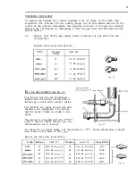
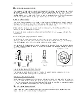
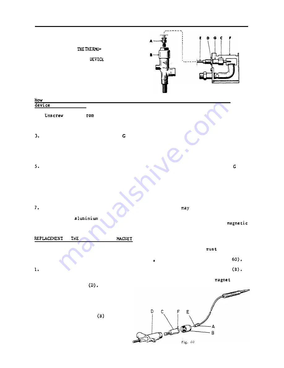
Fig. 59
replace the
thermo-element of the thermoelectric flame failure safety
( s e e f i g . 5 9 ) .
1.
plug
A
f
the valve housing
B .
2.
Loosen
the position nut C and lock nut
D .
Screw
off nut C, remove spacer and nut D. Release the thcrmo-element E from
burner housing F.
4.
Bend carefully the new thermo-element to the same shape as the old one.
S c r e w
nut D into
the new
element,
Put the feeler through the hole in the burner housing F, refit the spacer and
screw the position nut C tight against the shoulder on the feeler, raking sure
the nut D is free during this operation,
6.
Tighten the lock
nut
D
against the burner housing
with a small wrench, if
necessary holding nut C vith
another wrench, Make sure the feeler is located
a s i n f i g u r e .
Check that no burrs are inside valve housing
B
which
cause leaks,
Screw plug A onto the valve housing
B ,
taking care not to damage the threaded
hole in the
cap of the housing, Plug A must
be
properly tightened to
the valve housing to ensure contact betveen the thermo-element and the
coil vithin the housing,
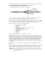
OF
SAFETY VALVE
If
the
safety valve magnet is defective, it cannot be repaired but
be replaced,
When the safety valve magnet needs replacement p r o c e e d
as
follows (see fig,
2.
3.
4.
Unscrew the connection plug
(A) on
the
thermocouple from the
housing nut
Unscrew the housing nut (B) and remove
the defective
safety valve
(C)
from the housing
Fit a new magnet valve and ensure
that it is properly inserted in
the housing (D).
Fit the housing nut
and the
connection plug
(A)
and
check
t h a t
a good contact
between the contact
plug (E)
on
the thermocouple and
the contact (F) on the safety
valve magnet is obtained.
Содержание RM24A
Страница 31: ...31 3 27 _ il ___ ____ 2 i Fig 51...


