


25
7,
8.
9.
10.
11.
12.
13.
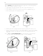
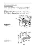
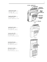
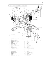
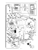
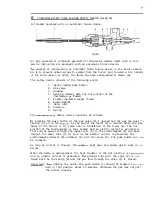
CAUTION :
1. Be sure to apply sealing permagum “A” (fig. 44 and fig. 45) on the unit mounting
plate and on the high evaporator inlet tube (B).
2.
Be sure to fit insulation pad (C) and sealing (D) (only on RM36C).
3. Be sure to apply proper amount of “Thermal Mastic” on the evaporator coil “E”
(fig. 44 and fig. 45).
4.
When fitting the evaporator flange(s) be sure to tighten the screws properly in
order to obtain a perfect contact between the evaporator coil and evaporator
flange, otherwise improper cabinet performance may result.
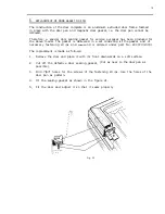
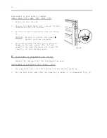
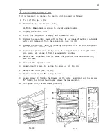
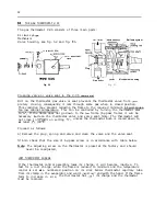
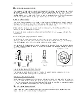
Remove the connection block cover on the side of the boiler case and disconnect
the
two electrical wires where they join the heater leads in the connection
block.
Remove the grounding screws “A” (see Fig. 46) on the lower part of the boiler
case.
Remove the flue and the flue baffle.
Remove the screws “B” (see Fig.
the cabinet.
46) holding the absorption unit onto the back of
Release the piezo electrode.
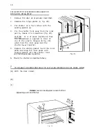
Carefully slide absorption unit out of cabinet. Be careful not to damage the
inner liner of the cabinet,
To replace absorption unit, reverse above procedure.
RM36C
Fig. 44
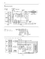
RM46, RM47
RM66, RM67
Fig. 1 5
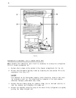
Содержание RM24A
Страница 31: ...31 3 27 _ il ___ ____ 2 i Fig 51...