4
LP GAS OPERATION
AES will select LP gas operation under the following
conditions:
No AC (230-240V) available
Engine not running (no high current at 12V DC available)
When the system chooses LP gas operation, the fl ame failure
device is automatically opened, allowing the gas to fl ow to the
burner. At the same time, the electronic igniter is energized.
After initial installation, servicing, or changing gas cylinders
etc., the gas pipes may contain some air that should be allowed
to escape by briefl y turning on the refrigerator or other appli-
ances. This will ensure that the fl ame lights immediately.
If the fl ame goes out (by gust of wind etc.), the reigniter will
automatically relight the fl ame.
NOTe! The control electronics and the igniter must have
12V DC (battery) supply to operate.
GAS TROUBLESHOOTING
If the Warning indicator lamp (
F
) is lit, there has been a failure
of gas operation. To troubleshoot, follow these steps:
Turn off the refrigerator. (Press the ON/OFF (
1
) to
“OFF”.)
Check that there is enough gas in the gas bottle, that its
valve is open and that any valves in the gas line to the
refrigerator are open.
Turn on the refrigerator again. (Press the ON/OFF button
(
1
) to “ON” .) After 10 sec. AES will repeat the ignition
sequence.
Should the warning lamp come on again after approx. 6
minutes, the failure is still present. Repeat the procedure
once
more. If this does not help, contact an authorised
service provider in your area.
ABNORMAL OPERATION
Any of the following are considered to be abnormal operation
and may require servicing:
Yellow tipping of the burner fl ame.
Sooting up area surrounding burner.
Burner not igniting properly.
Burner failing to remain alight.
In case the appliance fails to operate correctly, contact an au-
thorised Dometic Service Centre.
230-240V OPERATION
When a mains connection is available, AES will select this.
Please note, that even being in AC mode, 12V DC is necessary
for the internal supply of the electronics.
12V OPERATION
AES will select the 12V mode of operation as soon as the
vehicle engine is running (detected by the alternator connection
of the fridge D+).
If the 12V DC goes down below 9V DC, the system will shut
down completely.
•
•
1.
2.
3.
4.
•
•
•
•
OPERATING INSTRUCTIONS
CONTROL PANEL
ON/OFF button (main power button)
AES/GAS mode selector button
Temperature selector button
AES mode indicator lamp
GAS mode indicator lamp
AC mode indicator lamp
DC mode indicator lamp
Temperature indicator lamp
Warning indicator lamp (gas failure)
AES
The refrigerator is equipped with an Automatic Energy
Selector (AES) controlling the operation and energy supply.
NOTe! 12V must always be available to supply the
electronics.
The system selects the available energy source in the order:
230-240V
12V
LP gas
Turn off the AES function if you want the refrigerator to run
on LP gas only.
STARTING THE REFRIGERATOR
Whilst mobile:
Do not operate the refrigerator on LP gas.
Turn off the gas bottle.
Press the ON/OFF button (
1
). The refrigerator starts in the
mode it was in when it was turned off.
Press the AES/GAS button (
2
) and LED (
A
) or (
B
) comes
on. Select AES or LP gas only by pressing the AES/GAS
button (
2
) once if necessary.
If a 230V-240V mains supply is available:
AES selects this as the energy source and LEDs (
A
) and
(
C
) come on.
When the vehicle’s engine is running, AES selects 12V
operation and LEDs (
A
) and (
D
) are illuminated unless
LP gas only operation has been selected manually.
If neither mains nor a 12V battery supply are available:
AES selects LP gas operation and LEDS (
A
) and (
B
)
come on.
LP gas-only operation can be selected by pressing the AES/
GAS button (
2
) until LED (
B
) comes on; the AES function is
then turned off and LED (
A
) goes out. The Temperature selec-
tor button (
3
) is used to set the electronic thermostat. The LEDs
(
e
) show the value set on the thermostat.
1.
2.
3.
A.
B.
C.
D.
e.
F.
1.
2.
3.
•
•
1.
2.
3.
•
•
•
E
OFF
ON
C
A
B
C
D
F
1
2
3
Fig. 1
OPERATING INSTRUCTIONS
Содержание RM 23455
Страница 2: ......
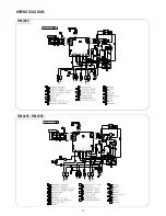
Страница 18: ...18 WIRING DIAGRAM RM 2355 RM 2455 RM 2555...
Страница 19: ...19 RM 4605 WIRING DIAGRAM...
Страница 22: ...22 Appendix A Airing position card RM 4605 1 2 5 4 3...
Страница 23: ...NOTES...
Страница 24: ......


