13
CONNECTION MARkED “CONNECT TO VEHICLE 12 VOLT DC BATTERY”
This connection supplies the 12 V DC heating element.
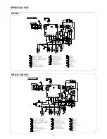
The (+12V) and (-) poles have to be connected directly to the
vehicle battery. (Via a suitable connection to the tow vehicle
when fitted to a caravan.)
The (+12V) supply wire, connected to the terminal block (S) on
the wiring diagrams, has to be fused according to the following
table:
Model
Fuse size (A)
RM2355
20
RM2455
20
RM2555
20
RM4605
30
Do not use the chassis for the return lead.
Cross-sections
The wires connected to this terminal must have the following
minimum cross section area:
RM 2355, RM 2455, RM 2555
Maximum length of 8 metres from refrigerator to the battery.
6 mm
2
cross-section low voltage multi strand cable.
RM 4605
Maximum length of 8 meters from refrigerator to the battery.
10 mm
2
cross-section low voltage multi strand cable.
Cable lengths longer than 8 meters will require larger cross-sec-
tional cable.
CONNECTION MARkED “CONNECT TO PERMANENT 12 VOLT DC
HOUSE BATTERY”.
This connection supplies the AES refrigerator control system
and must not be interrupted at any time whilst using the refrig-
erator on 240 volt, gas, and 12 volt. This is a permanent 12 volt
connection.
The (+12V) and (-) poles have to be connected directly to the
permanent 12 V DC house battery.
Do not use the chassis for the return lead.
The 12V supply must not be connected to a voltage controller
or similar device as the AES control system itself monitors the
DC voltage.
The +12V must be permanently attached and must not be cut
out when the ignition key is turned off. All connections should
be screwed or soldered to keep voltage drop to a minimum.
Cross-sections
The wires connected to this terminal must have a minimum
cross-section area of 1.5 mm
2
.
D+ CONNECTION
The connection D+ (alternator) has to be connected to the cor-
responding outlet of the vehicles electrical system - either a
12 V or a 24V DC alternator. The D+ connection accepts
24 V. Please note that the refrigerator accepts 12 V only. Do not
connect the refrigerator to 24 V!
This connection provides a signal to the refrigerators AES
control system informing the control system when the vehicle
engine is running.
The AES refrigerator can not select 12 V as the energy source
unless the vehicle engine is running.
Cross-sections
The D+ (alternator) is a signal cable and therefore 1-1.5 mm
2
is
sufficient.
•
•
ELECTRICAL CONNECTION
The electrical installation must be carried out by authorised
personnel.
NOTe! For mains voltage operation, it is important that
the circuit to and in the motorhome is effectively earthed.
The refrigerator is equipped with a three-prong (grounding)
plug for your protection against shock hazards and should be
plugged directly into a properly grounded threeprong recep-
tacle. DO NOT cut off or remove the grounding prong from
this plug.
If the supply cord is damaged, it must be replaced by the manu-
facturer, its service agent or similarly qualified persons in order
to avoid a hazard.
230-240V SUPPLIES
Check that the voltage stated on the data plate is the same as
the main voltage in use (230-240V).
NOTe! electrical leads must be routed and secured so that
they cannot come into contact with hot or sharp parts of
the refrigerator.
The free length of the cord is 1 m. It is
recommended that the receptacle is located
on the left side of the refrigerator (viewed
from the rear) and approximately 150 mm
from the floor. This allows easy access
through the vent door. The cord should
be routed to avoid direct contact with
the burner cover, flue cover or any other
components that could damage the cord
insulation.
12V AND “D+” CONNECTION
The refrigerator is equipped with two terminals intended for
connection to 12 volt. One is marked “Connect to permanent
12 Volt DC house battery”and the other is marked “Connect to
Vehicle 12 Volt DC battery”, see Fig. 19
NOTe!
For a Motor Home the house battery and the vehicle
battery may be the same battery.
For a caravan the 12 volt connections can only be made
to separate batteries.
•
•
230-240V AC
receptacle
100-
150mm
Fig. 18
Fig. 19
D+ signal from either a
12V or a 24V DC alternator.
D+D+
Only 12V DC to the PC board.
Under no circumstances can
24V DC be connected to the
PC board.
Connect to permanent
12 Volt DC house battery
Connect to Vehicle
12 Volt DC battery
Содержание RM 23455
Страница 2: ......
Страница 18: ...18 WIRING DIAGRAM RM 2355 RM 2455 RM 2555...
Страница 19: ...19 RM 4605 WIRING DIAGRAM...
Страница 22: ...22 Appendix A Airing position card RM 4605 1 2 5 4 3...
Страница 23: ...NOTES...
Страница 24: ......


