Configurable Safety System SAFEMASTER PRO
30
0265525 / 16.05.19 en / 101A
INPUTS
DESCRIPTION OF THE SIGNALS
MASTER ENABLE
NODE SEL
The control unit UG 6911.10 control unit has two inputs: MASTER_ENABLE1 and MASTER_ENABLE2:
The NODE_SEL0 and NODE_SEL1 inputs (on the expansion units) are used to attribute a physical address to
the expansion units with the connections shown in Table :
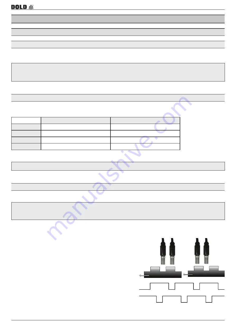
Configuration with Interleaved Proximity
A max. of 4 adresses and thus a max. of 4 modules of the same type can be used in one system
These signals must both be permanently set to logic level 1 (24 V DC) for the SAFEMASTER PRO to
operate. If the user needs to disable the SAFEMASTER PRO simply lower these inputs to logic level 0
(0VDC).
It is not allowed to use the same physical address on two units of the same type.
NODE_SEL0
NODE_SEL1
NODE 0
0 (oder not connected)
0 (oder not connected)
NODE 1
24 V DC
0 (oder not connected)
NODE 2
0 (oder not connected)
24 V DC
NODE 3
24 V DC
24 V DC
Proximity input for speed controller
When an axis of the UG 6917 is configured for a measurement with two proximity switches, these can
be configured in interleaved mode. Under the conditions listed below the system reaches a Performance
Level = PLe:
• Proximity switches must be fitted such that the recorded signals overlap.
• Proximity switches must be fitted such that at least one is always activated.
In addition:
• The proximity switches must be PNP type.
• The proximity switches must be NO type
(Output ON when detecting metal).
• With the above conditions fulfilled, the DC value is equal to 90 %.
• The two proximity switches must be of the same model, with
MTT
F
> 70 years.
Содержание Safemaster Pro
Страница 8: ...Configurable Safety System SAFEMASTER PRO 8 0265525 16 05 19 en 101A...
Страница 198: ...Configurable Safety System SAFEMASTER PRO 198 0265525 16 05 19 en 101A DECLARATION OF CONFORMITY...
Страница 199: ...Configurable Safety System SAFEMASTER PRO 199 0265525 16 05 19 en 101A DECLARATION OF CONFORMITY...


